background image

20

Gas Connection

Any gas installation must be carried out by a Gas Safe Registered engineer.

Connection to the gas supply should be with either rigid or semi-rigid pipe, i.e. steel or copper.  
The connection should be suitable for connecting to 1/2 inch BSP male thread. When the final 
connection has been made, it is essential that a thorough leak test is carried out on the hob and 
installation. Ensure that the main connection pipe does not exert any strain on the hob.

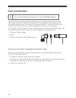
It is important to install the elbow correctly, with the shoulder on the end of the thread, fitted to the 
hob connecting pipe. Failure to ensure the correct assembly will cause leakage of gas.

1.  90 degree connection elbow

2.  Washer

3.  End of manifold with 1/2 inch BSP male thread 

Check the Hob After Installation & Before Using

When the hob has been fully installed it will be necessary to check the minimum flame setting.  
To do this, follow the step below,

1.  Turn the gas tap to the maximum position and ignite

2.  Set the gas tap to the minimum flame position then turn the control from minimum to maximum 

several times. If the flame is unstable or is extinguished adjust the gas rate. 

3.  Perform a gas tightness test.

1

2

3

Summary of Contents for S5GONGB13

Page 1: ...Instruction Manual 5 Burner Gas Hob S5GONGW13 S5GONGB13...

Page 2: ...9 If the Flame is Irregular 9 Cookware Guidelines 10 Cleaning and Maintenance 11 Cleaning Burner Parts and Pan Supports 12 Replacing the Burners 12 Hob Controls 12 Hints and Tips 13 Specifications 14...

Page 3: ...3 Conversion from NG to LPG or from LPG to NG 21 Method 21 Adjusting the Gas Rate 21 Burner Configuration Table 22...

Page 4: ...d wiring If the mains cable gets damaged it should be replaced by an authorized service agent or qualified electrician in order to avoid a hazard The hob must be used in a well ventilated location and...

Page 5: ...ay with the appliance The appliance and its accessible parts become hot during use Young children should be kept away Unattended cooking on a hob with fat or oil can be dangerous and may result in fir...

Page 6: ...u must spend some time reading this manual in order that you fully understand all the operational features it offers Read all the safety instructions carefully before use and keep this manual for futu...

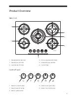
Page 7: ...2 Small Burner 45 mm 3 Large Burner 90 mm 4 Extra Large Burner 125 mm 5 Standard Burner 65 mm 6 Control Panel 1 Selects front left burner 2 Selects back left burner 3 Selects centre burner 4 Selects b...

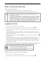
Page 8: ...d the control in for approximately 5 10 seconds after the burner has lit before adjusting to the desired setting Releasing the control too soon will extinguish the flame due to the flame failure safet...

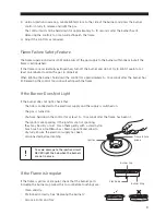
Page 9: ...he control too soon will extinguish the flame If the Burner Does Not Light If the burner does not light check that The hob is connected to the electrical supply and the supply is switched on The gas i...

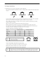
Page 10: ...the High position Once the food is boiling reduce the temperature to maintain a steady heat to cook your food thoroughly Doing this will reduce the cooking time and save energy Pan sizes should be as...

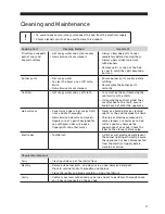
Page 11: ...shaft ensure liquid does not enter the appliance Hob surfaces Soak stains under a hot soapy cloth rinse and dry thoroughly Non abrasive hob surface cleaners Regular use of a polish designed for use wi...

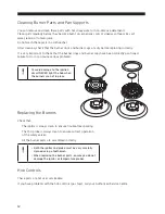
Page 12: ...positioned Failure to do so can cause serious problems To avoid damage to the ignition circuit NEVER light the hob when the burners are not in place Replacing the Burners Check that The ignitor is al...

Page 13: ...pproved service agent or installer One of my burners has an uneven flame Check the burner parts are clean and dry Check the assembly and make sure the burner cap is sitting flat My burner goes out whe...

Page 14: ...nal Product Dimensions cm Width x Depth 68 x 50 Internal Product Dimensions cm Width x Depth 55 x 47 Features and specifications are subject to change without prior notice Nominal Heat Input Chart Bur...

Page 15: ...ter installation or an all pole disconnection switch must be provided in the fixed wiring in accordance with the local wiring regulations The mains cable must not touch any hot parts Ensure that your...

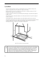
Page 16: ...o the cooker must be made of heat resistant material check with your furniture supplier The veneered synthetic material and the glue used must be resistant to a temperature of 150 C in order to avoid...

Page 17: ...e instructions or any of the other safety instructions incorporated in this manual are ignored Connect the threaded elbow to the gas supply input if required The washer supplied must be fitted between...

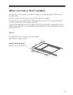
Page 18: ...erlap 5 Remove the backing strip from the sealing tape and carefully fit the hob into the aperture 6 Fit the four brackets to the underside of the hob Insert the hooked edge of the bracket into the sl...

Page 19: ...coloured in accordance with the following code The wire which is coloured green and yellow must be connected to the terminal marked E Earth The wire which is coloured blue must be connected to the ter...

Page 20: ...all the elbow correctly with the shoulder on the end of the thread fitted to the hob connecting pipe Failure to ensure the correct assembly will cause leakage of gas 1 90 degree connection elbow 2 Was...

Page 21: ...2 Isolate the hob from the electrical supply 3 Remove all pan supports burner caps rings crowns and controls 4 With the aid of a 7 mm box spanner the burner injectors can then be unscrewed and replace...

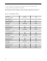
Page 22: ...ormal Pressure mbar 28 30 37 20 Extra Large Burner Injector Diameter mm 0 90 1 21 Nominal Rating W 3100 3100 Consumption 225 222 gr h 295 lt h Large Burner Injector Diameter mm 0 83 1 17 Nominal Ratin...

Page 23: ......

Page 24: ...recycling in the EU For more information please contact the local authority or your retailer where you purchased the product Visit Partmaster co uk today for the easiest way to buy electrical spares...

Reviews: