background image

Installation, Operation & Maintenance Manual                                                             Merlin Gas Detector-X 


DETX-IOM Iss: 7   02-21 

8  

   Detector Chain ID Switches 

 
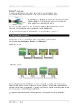
When wiring multiple detectors in a chain it is important to identify 
each and every detector installed for the control panel to receive and 
display accurate data corresponding with the correct detector type.  
 
The ID configuration diagram is printed onto detector boards for quick 
reference. All detectors are factory set to ID1. 
 
ID Switches must be configured for each and every 
detector connected to receive and display accurate data! 


We recommend a plan, map and/or marking the detector enclosures detailing ID and location! 


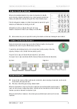
   120ohm Termination Resistance 


Signal communication issues may occur where the bus length is too long, high 
baud rates are used or signal reflections are occurring.  
 
To avoid this, terminating at each end of a chain may help the quality of the data 
signal by turning on the 120ohm terminal resistor switch. 
 
If a split chain is used, terminate the last detector in each chain.  
If a single chain is used, terminate the first device (Panel) and last device (Detector). 
 

Split chain                                                                                                  Single chain  


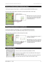
   Quick Circuit Test  


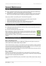
Access to the interior of the control panel or detector, when carrying out any work, must only be 
conducted by trained personnel. 


This does not test the gas sensing element itself. 

When the test button on the circuit board is pressed and held the detector will simulate an 
open circuit to ensure configured systems, outputs, alarms, indications and other external 
devices operate as intended in response to gas.  
 
When the test button is released – the test sequence will terminate and return to normal 
operation.  


Summary of Contents for MERLIN CO DETECTOR X

Page 1: ...n we supply a full range of remote gas detectors including carbon monoxide CO natural gas methane NG hydrogen H oxygen O2 and liquid petroleum gas LPG that are compatible with our range of Merlin control panels The information contained within this manual should be referenced for typical installation and operation only For specific requirements that may deviate from the information in this guide c...

Page 2: ...ance 8 Quick Circuit Test 8 Wiring your Detector GDP2 or GDP4 Control Panel 9 Wiring your Detector Merlin S Control Panels 9 Audible Alarm Switch 9 Factory Set Condition 10 Quick Installation Tips 10 Operation 11 Initial Power Up Commissioning 11 Gas Level Indication 11 Gas Alarm Levels 11 General Maintenance 12 Cleaning 12 Manual Simulation Test 12 Bump Test Gas Response Check 12 Service Calibrat...

Page 3: ...l and workmanship for a period of three 3 years from date of purchase or one 1 years for oxygen detectors The manufacturer s liability hereunder is limited to replacement of the product with repaired product at the discretion of the manufacturer This warranty is void if the product has been damaged by accident unreasonable use neglect tampering or other causes not arising from defects in material ...

Page 4: ...e device is not intended approved for use in potentially explosive atmospheres Typical Location and Positioning Locations for detectors will vary based on the intended application and target gas they should be located near identified sources of a potential gas leaks pockets where hazardous gas could quickly accumulate and areas of identified consequential risk The composition of the target gas and...

Page 5: ...rear cover mark the screw holes to the wall Ensure the wall surface is flat to prevent base distortion 3 There are two pre fractured areas for cable entry provided on the inside of the rear cover which may be cut away as required 4 After executing the mounting and the connections replace the rear cover ensuring the two clips are latched 5 Make a note of the installation date on the label located o...

Page 6: ...or MODBUS communications a shielded cable is used Wiring your Detector GDP2X or GDPX Control Panel 12 24VDC power and Modbus communication data cables are wired to Merlin gas detection panels GDP2X or GDPX Both terminals are identified as DETECTOR CHAIN D D If devices are not grounded they can give false readings or become a safety hazard Where connections may exceed 100 metres from one control pa...

Page 7: ...shielding or wiring mains power next to Modbus wiring To ground the data cable the shield should be connected to Power terminals Creating a Detector Chain Create a detector chain by connecting detectors in a parallel daisy chain method Any other way may cause issues or damage to the overall system Single chain example Split chain example Reversing the D and D connections of any device can lead to ...

Page 8: ...s length is too long high baud rates are used or signal reflections are occurring To avoid this terminating at each end of a chain may help the quality of the data signal by turning on the 120ohm terminal resistor switch If a split chain is used terminate the last detector in each chain If a single chain is used terminate the first device Panel and last device Detector Split chain Single chain Qui...

Page 9: ...ply via terminal GDP and S panel GAS DETECTOR terminal Connections should be made to the BMS relay COM and NC and Panel open close These are volt free connections to building management systems A relay will change state when in alarm or when gas is detected BMS terminals can be used in conjunction with other external relays that affect other devices and controls such as purge fans and audible alar...

Page 10: ...DBUS communications a shielded and twisted pair cable is used The shielding can be of 2 types braided like a mesh of thin conducting wires or like a foil consisting of a thin sheet of metal covering the twisted wires PROTECTION High concentrations of alcohol found in many products may damage deteriorate or affect the gas sensing elements of Detectors such as wine deodorants stain removers thinners...

Page 11: ...ed engineers to ensure correct installation and operation The Merlin range of gas detectors are optimum calibrated when manufactured However we strongly recommend the detectors response and fault conditions are tested and validated once installed This will ensure the equipment is performing as intended and free from unforeseen damage caused by transit installation Gas Level Indication Gas Alarm Le...

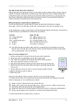
Page 12: ...tector will simulate an open circuit to ensure configured systems outputs alarms indications and other external devices operate as intended in response to gas When the test button is released the test sequence will terminate and return to normal operation Bump Test Gas Response Check What is a Gas Response Check Response checks are often referred to as a BUMP TEST Bump tests are important to make ...

Page 13: ...ssified as non flammable and non toxic however they do contain gas under pressure and may explode if heated to extreme temperatures and cause asphyxiation in high concentrations How do I conduct a Bump Test 1 Ensure you have the correct gas for the device type prior to application 2 Screw and seal the regulator valve into the gas cylinder outlet 3 Once sealed the regulator pressure gauge will indi...

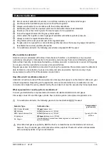
Page 14: ...quipment in accordance with Safety Data Sheets Detector Service Message A service screen will intermittently flash every 30 seconds after one year of operation The detector will still operate as intended during this time This message prompts a recommended service and calibration of the gas sensor to ensure operational accuracy Enter Service Mode GDP2X GDPX ONLY When service mode is activated the c...

Page 15: ...l failure Regular gas sensor recalibration is important to prolong the operational life and make sure the detector is able to detect a concentration of gas as accurately and early as possible Typical accuracy of gas measurement is within 10 of the detected concentration How often shall I recalibrate a detector Calibration should coincide with the annual service message that appears on the detector...

Page 16: ...a Short out the Cal1 header to enter calibration mode during the initial warm up period b Offer up the applicator hose cone to the gas sensor c Open the valve regulator to allow the gas to be delivered at a pre set flow rate d The screen will display a SUCCESSFUL text when the calibration is complete e Remove applicator hose cone and turn the gas cylinder regulator valve off f On the control panel...

Page 17: ...quency of exposure to the target gas poisons or inhibitors At the end of their working life electrochemical sensors for oxygen and carbon monoxide detectors should be disposed of in an environmentally safe manner Alternatively all detectors can be securely packaged and returned to S S Northern clearly marked for disposal Electrochemical sensors should not be incinerated as this may cause the cell ...

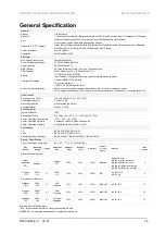
Page 18: ...at end of expected sensor life Construction Dimensions H x W x D 140 x 95 x 30mm 5 51 x 3 74 x 1 18 Unit Weight Approx 0 05kg 1 77oz Nominal Orientation Wall Mounted No Limits Housing Material Polylac PA765 Environmental Ingress Protection IP40 Storage Conditions Dry Temp 20 50 C 4 122 F RH 15 90 Sensor Operating Temperature 20C 50 C 4 122 F Sensor Operating Humidity Continuous 30 80 RH Non Conden...

Page 19: ...Installation Operation Maintenance Manual Merlin Gas Detector X DETX IOM Iss 7 02 21 19 Page intentionally left blank ...

Page 20: ... range of gas detectors are optimum calibrated when manufactured However we strongly recommend the detectors response and fault conditions are tested and validated once installed This will ensure the equipment is performing as intended and free from unforeseen damage caused by transit installation S S Northern Head Office Tel 44 0 1257 470 983 Fax 44 0 1257 471 937 www snsnorthern com info snsnort...

Reviews: