Sandpiper G Series Service & Operating Manual Download Page 2

g05mdl1sm-rev0717

sandpiperpump

.

com

IMPORTANT

Read the safety warnings and instructions in this manual 

before pump installation and start-up. Failure to comply with 

the recommendations stated in this manual could damage the 

pump and void factory warranty.

When used for toxic or aggressive fluids, the pump should 

always be flushed clean prior to disassembly.

Airborne particles and loud noise hazards. Wear eye and ear 

protection.

Before maintenance or repair, shut off the compressed gas line, 

bleed the pressure, and disconnect the gas line from the pump. 

Be certain that approved eye protection and protective clothing 

are worn at all times. Failure to follow these recommendations 

may result in serious injury or death.

ATEX compliant pumps are suitable for use in explosive atmospheres when the equipment is properly grounded 

in accordance with local electrical codes. Pumps equipped with electrically conductive diaphragms are suitable for 

the transfer of conductive or non-conductive fluids of any explosion group. When operating pumps equipped with 

non-conductive diaphragms that exceed the maximum permissible projected area, as defined in EN 13463-1:  2009 

section 6.7.5 table 9, the following protection methods must be applied:

•  Equipment is always used to transfer electrically conductive fluids or

•  Explosive environment is prevented from entering the internal portions of the pump, i.e. dry running

For further guidance on ATEX applications, please consult the factory.

When the pump is used for materials that tend to settle out 

or solidify, the pump should be flushed after each use to 

prevent damage. In freezing temperatures the pump should be 

completely drained between uses.

Before pump operation, inspect all fasteners for loosening 

caused by gasket creep. Retighten loose fasteners to prevent 

leakage. Follow recommended torques stated in this manual.

CAUTION

WARNING

Nonmetallic pumps and plastic components are not UV 

stabilized.  Ultraviolet radiation can damage these parts and 

negatively affect material properties. Do not expose to UV light 

for extended periods of time.

In the event of diaphragm rupture, pumped material may enter 

the air end of the pump, and be discharged into the atmosphere. 

If pumping a product that is hazardous or toxic, the air exhaust 

must be piped to an appropriate area for safe containment.

This pump is pressurized internally with gas pressure during 

operation. Make certain that all fasteners are in good condition 

and are reinstalled properly during reassembly.

Take action to prevent static sparking. Fire or explosion can 

result, especially when handling flammable liquids. The pump, 

piping, valves, containers and other miscellaneous equipment 

must be properly grounded.

Safety Information

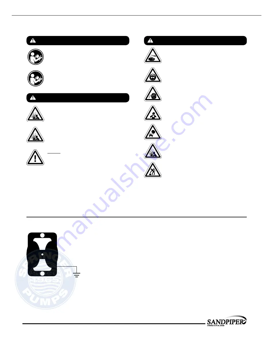
Grounding ATEX Pumps

Use safe practices when lifting

kg

WARNING

The use of non-OEM replacement parts will void (or negate) 

agency certifications, including CE, ATEX, CSA, 3A and EC1935 

compliance (Food Contact Materials).  Warren Rupp, Inc. cannot 

ensure nor warrant non-OEM parts to meet the stringent 

requirements of the certifying agencies. 

UNIVERSAL ALL AODD

Tel:  866-777-6060 
Fax: 866-777-6383

Springer Pumps, LLC

Website: www.springerpumps.com 

Int'l: +001 267 404 2910

Summary of Contents for G Series

Page 1: ...61 5 60 142 32 3 12 79 12 DISCHARGE PORT 1 2 NPT AIR INLET 1 4 NPT Warren Rupp Inc A Unit of IDEX Corporation 800 N Main St Mansfield Ohio 44902 USA Telephone 419 524 8388 Fax 419 522 7867 SANDPIPERPUMP COM Copyright 2017 Warren Rupp Inc All rights reserved Certified Quality Certified to CSA Technical Letter No R 14 Certified to ANSI LC6 2008 ISO 9001 Certified ISO 14001 Certified SERVICE OPERATIN...

Page 2: ...sed for materials that tend to settle out or solidify the pump should be flushed after each use to prevent damage In freezing temperatures the pump should be completely drained between uses Before pump operation inspect all fasteners for loosening caused by gasket creep Retighten loose fasteners to prevent leakage Follow recommended torques stated in this manual CAUTION WARNING Nonmetallic pumps a...

Page 3: ...arts List Material Codes SECTION 4 GAS END 12 Aluminum Gas Valve Assembly Stainless Steel Gas Valve Assembly Pilot Valve Assembly Intermediate Assembly SECTION 5 WET END 15 Diaphragm Drawings Diaphragm Servicing Pumping Hazardous Liquids SECTION 7 WARRANTY CERTIFICATES 18 Warranty CE Declaration of Conformity Machinery ATEX Declaration of Conformity MODEL SPECIFIC 1 PUMP SPECS 2 INSTAL OP 3 EXP VI...

Page 4: ...ess Steel Diaphragm Check Valve Materials B Nitrile Nitrile T PTFE Overlay Nitrile PTFE 5 Nitrile PTFE Check Valve Seat T Virgin PTFE A Aluminum S Stainless Steel Your Serial fill in from pump nameplate ______________________________________ Pump Pump Check Design Wetted Diaphragm Check Valve Non Wetted Porting Pump Muffler Pump Brand Size Valve Level Material Check Valve Seat Material Options Sty...

Page 5: ...cally inert virtually impervious Very few chemicals are known to chemically react with PTFE molten alkali metals turbulent liquid or gaseous fluorine and a few fluoro chemicals such as chlorine trifluoride or oxygen difluoride which readily liberate free fluorine at elevated temperatures 220 F 104 C 35 F 37 C Maximum and Minimum Temperatures are the limits for which these materials can be operated...

Page 6: ... Are Available In 1 2 BSPT Tapered Internal 1 BSPT Tapered External Note The pump is to be mounted in a horizontal position Gas Inlet 1 4 NPT Discharge Port 1 2 NPT Internal 1 NPT External 3 8 NPT For Piping Exhausted Natural Gas Suction Port 1 2 NPT Internal 1 NPT External Both Suction and Discharge Ports Are Available In 1 2 BSPT Tapered Internal 1 BSPT Tapered External FRONT VIEW BOTTOM VIEW SI...

Page 7: ...XHAUST 5 50 139 70 6 12 155 45 8 44 214 31 7 19 182 56 R 19 4 83 10 48 266 17 6 90 175 13 1 76 44 61 5 60 142 32 3 12 79 12 DISCHARGE PORT 1 2 NPT AIR INLET 1 4 NPT BOTTOM VIEW 5 60 142 32 9 89 251 19 10 24 260 14 1 42 36 12 10 54 267 83 10 87 275 99 SUCTION PORT 1 2 NPT SUCTION PORT OPTIONAL 1 2 NPT DISCHARGE PORT OPTIONAL 1 2 NPT 1 NPT EXTERNAL PIPE THREADS 3 8 NPT AIR EXHAUST 5 50 139 70 6 12 1...

Page 8: ...EQ SPACED ON A 2 38 60 BOLT CIRCLE SUCTION PORT 1 2 RF ANSI 150 FLANGE 4X 62 16 HOLES EQ SPACED ON A 2 38 60 BOLT CIRCLE AIR INLET 1 4 NPT 8 75 222 5 50 140 7 19 183 7 75 197 7 19 183 4X 38 10 MTG HOLE 10 26 261 2 00 51 9 19 233 1 25 32 11 54 293 34 9 9 79 249 3 8 NPT AIR EXHAUST 3 08 78 3 78 96 38 10 12 54 319 1 42 36 3 06 78 3 78 96 6 12 155 5 60 142 9 79 249 10 48 266 DISCHARGE PORT 1 2 RF ANSI...

Page 9: ...e stroking also initiates the reciprocating shifting stroking or cycling action of the pump The suction diaphragm s movement is mechanically pulled through its stroke The diaphragm s inner plate makes contact with an actuator plunger aligned to shift the pilot signaling valve Once actuated the pilot valve sends a pressure signal to the opposite end of the main directional gas valve redirecting the...

Page 10: ...o obtain the most efficient gas flow to pump flow ratio Recommended Installation Guide Top Discharge Ball Valve Pump Natural Gas Exhaust Natural Gas Inlet Natural gas supply conductive piping must be supported Gas Shut Off Valve Available from Warren Rupp 2 1 Flexible Conductive Connection Regulator w Gauge Filter Pipe Connection Style Optional Gauge Shut Off Valve SUCTION Drain Port Flexible Conn...

Page 11: ... Pump is designed for 1 1 pressure ratio at zero flow Does not apply to high pressure 2 1 units Cavitation on suction side Check suction move pump closer to product Lack of gas line size PSI CFM Check the gas line size length compressor capacity Excessive suction lift For lifts exceeding 20 of liquid filling the chambers with liquid will prime the pump in most cases Gas supply pressure or volume e...

Page 12: ...ted End Kit Nitrile Diaphragm PTFE Overlay Diaphragm PTFE Check Balls and PTFE Seats 476 238 672 Wetted End Kit Nitrile Diaphragms PTFE Check Balls PTFE Seats OVERLAY OPTION Torque 70 in lbs 7 9 N m Torque 120 in lbs 13 N m Torque 70 in lbs 7 9 N m 476 318 000 Gas End Wear Kit Nitrile 0 rings Bumpers and Seals 476 318 363 Gas End Wear Kit FKM 0 rings Bumpers and Seals 474 095 360 Wet End Wear Kit ...

Page 13: ... Manifold Suction BSP Tapered SS 1 518 158 110W Manifold Suction 1 2 Welded Raised Face 150 ANSI Flanged SS 1 24 518 159 110 Manifold Discharge SS 1 518 159 110E Manifold Discharge BSP Tapered SS 1 518 159 110W Manifold Discharge 1 2 Welded Raised Face 150 ANSI Flanged SS 1 Item Part Number Description Qty 25 545 004 330 Nut Hex Flanged 5 16 18 Alum 24 545 004 330 Nut Hex Flanged 5 16 18 SS 8 26 5...

Page 14: ... Nitrile 368 Food Grade EPDM 371 Philthane Tuftane 374 Carboxylated Nitrile 375 Fluorinated Nitrile 378 High Density Polypropylene 379 Conductive Nitrile 408 Cork and Neoprene 425 Compressed Fibre 426 Blue Gard 440 Vegetable Fibre 500 Delrin 500 502 Conductive Acetal ESD 800 503 Conductive Acetal Glass Filled 506 Delrin 150 520 Injection Molded PVDF Natural color 540 Nylon 542 Nylon 544 Nylon Inje...

Page 15: ...ews 1 E Step 2 Remove end cap 1 D and bumper 1 C Step 3 Remove spool part caution do not scratch Step 4 Press sleeve 1 A from body 1 B Step 5 Inspect O Ring 1 F and replace if necessary Step 6 Lightly lubricate O Rings 1 F on spool 1 A Step 7 Press sleeve 1 A into body 1 B Step 8 Reassemble in reverse order starting with step 3 Note Sleeve and spool 1 A set is match ground to a specified clearance...

Page 16: ...00 Pilot Valve Assembly 1 3 A 095 087 157 Valve Body 1 3 B 755 051 000 Sleeve With O Rings 1 3 C 560 033 360 O Ring Sleeve 6 3 D 775 055 000 Spool With O Rings 1 3 E 560 023 360 O Ring Spool 3 3 F 675 037 080 Retaining Ring 1 Item Part Number Description Qty 3 095 116 363 Pilot Valve Assembly FKM 1 3 B 755 051 363 Sleeve With O Rings FKM 1 3 C 560 033 363 O Ring FKM 6 3 D 775 055 363 Spool With O ...

Page 17: ... Step 2 Remove Ring Retaining 31 discard Step 3 Remove bushing plunger 7 inspect for wear and replace if necessary with genuine parts Step 4 Remove O Ring 26 inspect for wear and replace if necessary with genuine parts Step 5 Lightly lubricate O Ring 26 and insert into intermediate Step 6 Reassemble in reverse order IMPORTANT When the pumped product source is at a higher level than the pump floode...

Page 18: ...bove Diaphragm Ori Intall diaphragm and overla Torque 120 in lbs Torque 120 in lbs 32 6 29 15 28 14 11 25 36 36 36 11 32 36 6 29 15 16 28 14 11 25 11 14 28 16 11 15 11 14 28 36 11 36 36 36 15 11 Diaphragm Orientation Intall diaphragm as shown above Diaphragm Orientation Intall diaphragm and overlay as shown above 120 in lbs Torque 120 in lbs MODEL SPECIFIC 5 WET END Tel 866 777 6060 Fax 866 777 63...

Page 19: ...ush the threaded outer diaphragm plate through the center hole of the diaphragm Note Most diaphragms are installed with the natural bulge out towards the fluid side S05 S07 and S10 non metallic units are installed with the natural bulge in towards the gas side Step 5 Thread or place outer plate stud into the inner plate For threaded inner plates use a torque wrench to tighten the assembly together...

Page 20: ... recommends installing a flexible conductive hose or connection between the pump and any rigid plumbing This reduces stresses on the molded threads of the natural gas exhaust port Failure to do so may result in damage to the natural gas distribution valve body Any piping or hose connected to the pump s natural gas exhaust port must be conductive and physically supported Failure to support these co...

Page 21: ...s Common Safety Requirements to verify conformance 5 YEAR Limited Product Warranty Warren Rupp Inc Warren Rupp warrants to the original end use purchaser that no product sold by Warren Rupp that bears a Warren Rupp brand shall fail under normal use and service due to a defect in material or workmanship within five years from the date of shipment from Warren Rupp s factory Warren Rupp brands includ...

Page 22: ...ge Suppressors Technical File No 203104000 1410 MER AODD Air Operated Double Diaphragm Pumps EC Type Examination Certificate No Pumps KEMA 09ATEX0071 X DEKRA Certification B V 0344 Meander 1051 6825 MJ Arnhem The Netherlands Applicable Standard EN13463 1 2001 EN13463 5 2003 EN60079 25 2004 Harmonised Standard EN13463 1 2009 EN13463 5 2011 EN60079 25 2010 David Roseberry Director of Engineering DAT...

Reviews: