background image

17

ESP

AÑOL

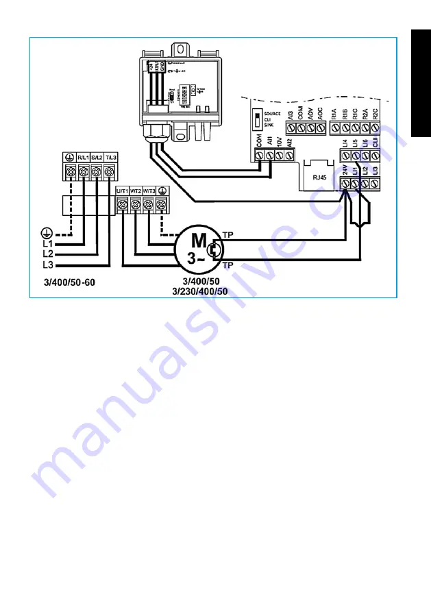
•  Comprobar que el interruptor “SW1” del variador de frecuencia está en la posición SOURCE.

ATENCIÓN: cuando se utilice un único variador de frecuencia para controlar 

dos motores los protectores térmicos se conectarán en serie.

6.7.2.2 CONfIGUraCIÓN DEl TraNsMIsOr DE PrEsIÓN DIfErENCIal 
            (TDP-s Y TDP-D)

•  Si se desea configurar el equipo para realizar un control a presión constante pueden em-

plearse los modelos de transmisor de presión diferencial TDP-S y TDP-D. Si se desea llevar 
a cabo un control a caudal constante únicamente se puede utilizar el modelo TDP-D.

  El conexionado de los tubos de presión dependerá del tipo de control requerido, tal y como 

se muestra en la siguiente figura

Summary of Contents for UTBS Series

Page 1: ...1 Serie UTBS Unidades de tratamiento de aire de bajo perfil Low profile air handling units Manual de instalaci n Instrucciones de uso Installation manual Instructions for use...

Page 2: ...TDP S 18 6 7 2 2 2 MODELO TDP D 19 6 7 2 2 3 CALIBRACI N DEL TRANSMISOR DE PRESI N TDP S Y TDP D 21 6 7 2 3 CONFIGURACI N DEL VARIADOR DE FRECUENCIA 21 6 7 2 3 1 AJUSTE DEL PUNTO DE TRABAJO 21 6 7 2 3...

Page 3: ...recomendamos a todas las personas expuestas a riesgos que se atengan escrupulosamente a las normas de prevenci n de accidentes en vigor en su pa s S P queda exento de cualquier responsabilidad por eve...

Page 4: ...s en movimiento y existe el peligro de enganchar alguna parte del cuerpo Indicaci n del sentido del aire en la unidad Indicaci n de entrada y salida del flui do del intercambiador t rmico de agua fr a...

Page 5: ...la unidad Antes de implantar el equipo en su lugar definitivo se comprobar que el lugar donde se va a ubicar el equipo es lo suficientemente resistente como para poder soportar el peso de ste No se i...

Page 6: ...seja emplazar la unidad en una ubicaci n d nde la instalaci n sea de f cil acceso Prever un espacio suficiente para el mantenimiento el conexionado y la evacuaci n de condensados 6 4 ESPACIO PARA MANT...

Page 7: ...0 410 UTBS 8 1900 500 Para el montaje en techo y suelo se deber suspender de las cuatro escuadras existentes en cada m dulo como sigue MONTAJE EN TECHO MONTAJE EN SUELO ATENCI N Debido a la longitud y...

Page 8: ...tes m dulos entre si Si el equipo est formado por diferentes m dulos se suministrar un kit de uni n compuesto por 4 juegos de tornillos arandelas tuercas y junta de estanqueidad 6 5 1 UNI N DE TEJADIL...

Page 9: ...r en paralelo en el caso de tener m dulo recu perador o m dulo free cooling el equipo vendr provisto de escuadras para unir los m dulos Para fijar dichas escuadras se deber acceder al equipo por el in...

Page 10: ...vez instalado el aparato debe cumplir con las Directivas siguientes Directiva de Baja Tension 2006 95 CE Directiva de M quinas 2006 42 CE Directiva de Compatibilidad Electromegn tica 2004 108 CE Reali...

Page 11: ...e aire La bater a deber ponerse en marcha cuando se alcance el caudal de aire m nimo o bien cuando la velocidad del aire dentro de la bater a sea superior a 1 5m s La instalaci n el ctrica no debe per...

Page 12: ...12 ESPA OL En el esquema adjunto se muestra como conectar las resistencias de la bater a el ctrica Conexionado electrico BE 2 15 kw 1 etapa catalogo Conexionado electrico BE 2 7 5 kw 2 etapas catalogo...

Page 13: ...13 ESPA OL Conexionado electrico BE 3 24 kw 1 etapa catalogo Conexionado electrico BE 3 24 kw 2 etapas catalogo...

Page 14: ...14 ESPA OL Conexionado electrico BE 5 18 kw 2 etapas catalogo Conexionado electrico BE 5 12 kw 3 etapas catalogo...

Page 15: ...15 ESPA OL Conexionado electrico BE 8 22 5 kw 2 etapas catalogo Conexionado electrico BE 8 15 kw 3 etapas catalogo...

Page 16: ...do 9 5 se muestra una tabla con los valores recomendados para la sustituci n de los filtros 6 7 2 CONTROL EN VENTILADORES El equipo dispone de 3 tomas de presi n para controlar el ventilador a caudal...

Page 17: ...guraci n del transmisor de presi n diferencial TDP S y TDP D Si se desea configurar el equipo para realizar un control a presi n constante pueden em plearse los modelos de transmisor de presi n difere...

Page 18: ...ubo de presi n m s alta tiene que conectarse al terminal y el de presi n m s baja al En caso de no realizarse de esta manera la presi n medida estar fuera de rango y la pantalla del transmisor parpade...

Page 19: ...selec ci n del rango de presi n deseado se realiza mediante los interruptores DIP1 DIP2 y DIP3 Rango de presi n Pa DIP 1 DIP 2 DIP 3 50 50 1 1 1 0 100 0 1 1 0 150 1 0 1 0 300 0 0 1 0 500 1 1 0 0 1000...

Page 20: ...lsar OK para guardar la configu raci n Los rangos de presi n seleccionables son los siguientes 50 50 Pa 0 100 Pa 0 150 Pa 0 300 Pa 0 500 Pa 0 1000 Pa 0 1600 Pa 0 2500 Pa Funcionamiento a caudal consta...

Page 21: ...e finalice el proceso de calibraci n Para llevar a cabo correctamente la calibraci n la presi n en los terminales y ha de ser la misma Se reco mienda que los tubos est n desconectados 6 7 2 3 Configur...

Page 22: ...llegar al men drC Pulse ENT y gire la rueda hasta el par metro tFr Pulse ENT y gire la rueda hasta un valor igual o superior al de la frecuencia de trabajo del equipo Pulse ENT y vuelva al men princip...

Page 23: ...ESC durante dos segundos hasta que los leds indicadores de modo parpadeen simult neamente A continuaci n desbloquee el variador Pulse ENT y gire la rueda hasta llegar al men SUP Pulse ENT y gire la r...

Page 24: ...de la corriente nominal nCr Men Par metro Observaciones drC bFr Frecuencia nominal ventilador drC UnS Tensi n nominal del motor que aparece en la placa de caracter sticas drC FrS Frecuencia nominal de...

Page 25: ...especifica una relaci n del tipo de rosca para cada modelo de UTBS MODELO ROSCA UTBS 2 2 4 y 6 filas 35x1 5 1 3 8 UTBS 3 2 4 y 6 filas 35x1 5 1 3 8 UTBS 5 2 4 y 6 filas 35x1 5 1 3 8 UTBS 8 2 4 y 6 fi...

Page 26: ...c sin obligar al vaciado de todo el circuito Se colocar n manguitos anti vibratorios en la entrada y la salida del equipo de tal forma que no se transmitan vibraciones que provoquen la rotura de las b...

Page 27: ...tada En primer lugar se pondr en funcionamiento la bomba de circulaci n de agua Esperar varios minutos hasta comprobar que el caudal de circulaci n permanece constante y no hay variaciones de caudal C...

Page 28: ...entido de giro marcado en el ventilador Si el sentido de giro no es el correcto intercambiar dos de las fases de fuerza Para realizar esta operaci n desconectar el interruptor de mando del equipo y el...

Page 29: ...E INTERCAMBIO T RMICO Al comenzar cada temporada verano e invierno comprobar que las aletas de las bater as no est n obstruidas por polvo pelusa u otros cuerpos extra os que impidan la circulaci n de...

Page 30: ...cia de partida y lo que se puede producir es un deterioro de los mismos Aunque el lavado o la aspiraci n en sentido contrario a la circulaci n habitual del aire puedan conseguir un acabado ptimo es ac...

Page 31: ...rsa 9 6 BATER AS Si se detecta cualquier anomal a en las bater as y tienen que ser extra das desatornillar los tornillos del panel donde van ubicadas extraer el panel y retirar las bater as Las bater...

Page 32: ...n 9 8 1 M DULO DE MEZCLAS M dulo de 2 v as Se env a siempre con una posici n fija de las compuertas si no coincide con las necesidades de la instalaci n cambiar el panel frontal tal y como se indica M...

Page 33: ...combusti n Asegurarse de que esto no pueda suceder y en su caso prever un sistema de alarma si se produce este hecho Se comprobar que el riego de los paneles tenga un exceso de agua que cae a la band...

Page 34: ...e su ubicaci n desl celo por sus gu as tirando de los ngulos y no de las aletas del intercambiador para no da arlo Limpie el intercambiador con aire comprimi do o con un aspirador y l velo con deterge...

Page 35: ...6 7 2 2 1 TDP S MODEL 51 6 7 2 2 2 TDP D MODEL 52 6 7 2 2 3 CALIBRATION OF THE PRESSURE TRANSMITTER TDP S and TDP D 54 6 7 2 3 CONFIGURING THE VARIABLE FREQUENCY DRIVE 54 6 7 2 3 1 SETTING THE WORKING...

Page 36: ...standards of a general nature Consequently we recommend that all personnel exposed to risks adhere strictly to local regulations in force regarding hazard prevention S P is in no way responsible for a...

Page 37: ...ors Kw Maximum absorbed current of motor A Power of installed electric heater Electrical supply 5 HANDLING When unit received unpack and make sure the packaging is intact any defect may indicate damag...

Page 38: ...ed and qualified service per sonnel may install service or repair the equipment As a precaution when performing operations inside the equipment shut off the power at a main breaker This serves to prev...

Page 39: ...condensate 6 4 MAINTENANCE SPACE The installer should leave sufficient unobstructed space to allow free access to the unit for maintenance The amount of space needed will depend on which side of the u...

Page 40: ...suspended from the four angle brackets on each module as follows CEILING MOUNTED FLOOR MOUNTED WARNING Due to the length and weight of the units each module must be suspended separately There should...

Page 41: ...g kit with 4 sets of bolts washers nuts and a sealing gasket 6 5 1 COVER SEAMS If you have ordered a climate control unit for outdoor usage the equipment will come equip ped with a rain proof cover If...

Page 42: ...supplied with joining brackets to join the modules to gether To attach these brackets the equipment must be accessed from the inside Place the bracket over the aluminium strip and tighten with the two...

Page 43: ...The equipment has glands on the sides where the power is connected for running power cables to the motors A power outlet fuse or U curve thermo magnetic breaker must be installed for each fan which wi...

Page 44: ...to place an air filter before the heating element The electrical installer must provide airflow control device so that the electrical heater ope rates when the minimum airflow is reached or when the...

Page 45: ...7 5 kW 2 steps STANDARD A HEATER ELEMENT 2 5 kW B THERMAL PROTECTION R A C THERMAL PROTECTION R M STANDARD A HEATER ELEMENT 2 5 kW B THERMAL PROTECTION R A C THERMAL PROTECTION R M Sample of connecti...

Page 46: ...0 kW B THERMAL PROTECTION R A C THERMAL PROTECTION R M STANDARD A HEATER ELEMENT 4 0 kW B THERMAL PROTECTION R A C THERMAL PROTECTION R M Sample of connection with regulator D REGULATOR TTC 40 F E SW...

Page 47: ...TECTION R A C THERMAL PROTECTION R M STANDARD A HEATER ELEMENT 4 0 kW B THERMAL PROTECTION R A C THERMAL PROTECTION R M Sample of connection with regulator D REGULATOR TTC 40 F D1 REGULATOR TT S4 E SW...

Page 48: ...ROTECTION R A C THERMAL PROTECTION R M STANDARD A HEATER ELEMENT 4 0 kW B THERMAL PROTECTION R A C THERMAL PROTECTION R M Sample of connection with regulator D REGULATOR TTC 40 F D1 REGULATOR TT S4 E...

Page 49: ...ers Section 9 5 presents a table with the values recommended for filter replacement 6 7 2 FAN CONTROLS The unit has 3 pressure taps to maintain the fan at a constant airflow or constant pressure To be...

Page 50: ...2 Configuring the differential pressure transmitter TDP S TDP D If you wish to configure the equipment to operate under constant pressure control you can use differential pressure transmitter models...

Page 51: ...ing this the pressure measured will be out of range and the transmitter screen will flash 6 7 2 2 1 TDP S Model Air direction CONSTANT PRESSURE CONTROL Leave one of the pressure taps unconnected CONST...

Page 52: ...elow The required pressure range is selected using the switches DIP1 DIP2 and DIP3 Pressure range Pa DIP 1 DIP 2 DIP 3 50 50 1 1 1 0 100 0 1 1 0 150 1 0 1 0 300 0 0 1 0 500 1 1 0 0 1000 0 1 0 0 1600 1...

Page 53: ...n to save the configuration The pressure ranges which may be selected are as follow 50 50 Pa 0 100 Pa 0 150 Pa 0 300 Pa 0 500 Pa 0 1000 Pa 0 1600 Pa 0 2500 Pa Constant flow operation Only available wi...

Page 54: ...until the calibration process is complete For a correct calibration the pressure in the and terminals must be the same It is recommended that the tubes are disconnected 6 7 2 3 Configuring the variab...

Page 55: ...urn the wheel until the value is greater than or equal to the equipment s working point frequency Press ENT and return to the main menu by pressing ESC twice Then enter the value of the equipment work...

Page 56: ...seconds until the mode indicator LEDs flash simultaneously Next unlock the inverter Press ENT and turn the wheel until you reach the SUP menu Press ENT and turn the wheel until you reach the COd para...

Page 57: ...control two motors double the value of the rated current nCr Menu Parameter Notes drC bFr Rated frequency of the fan drC UnS Rated voltage of the motor as shown on the name plate drC FrS Rated frequen...

Page 58: ...llowing table gives a list of the types of thread for each UTBS MODEL THREAD UTBS 2 2 4 or 6 pipes 35x1 5 1 3 8 UTBS 3 2 4 or 6 pipes 35x1 5 1 3 8 UTBS 5 2 4 or 6 pipes 35x1 5 1 3 8 UTBS 8 2 4 or 6 pi...

Page 59: ...c and avoid the need to completely drain the water circuit Anti vibration bellows should be installed at the inlet and outlet from the unit to prevent the transmission of vibrations that could result...

Page 60: ...dy and that there is no variation in the flow Make sure that any air bubbles have been drawn to the bleed points and that they have been bled off Make sure that the pressures in the unit do not exceed...

Page 61: ...rn the unit on again Test fan and motor rotation speed using a tachometer Make sure that the unit receives adequate air flow or else its performance will be seriously compromised With the unit running...

Page 62: ...s to a specific training programme Before starting maintenance operations on the unit turn off the unit s main switch Electrical shock can cause personal injury Keep the following in mind when perform...

Page 63: ...ed It is not recommended that filters be washed since they will never recover their initial effi ciency and doing so can produce wear on the filters Although washing or vacuuming in the opposite direc...

Page 64: ...the coils and they need to be removed loosen the bolts from the panel where they are located remove the panel and extract the coils The coils are installed in slod for easy slide in and slide out 9 7...

Page 65: ...ODULE Air 2 inlet section Is sent with a fixed position of the dampers If not coincide with the needs of the installation change the frontal panel as shown Air 3 inlet section A B When it is installed...

Page 66: ...AY WITH BASE AND ROOF Damper as standard supplied left hand If required right hand installer can change posi tion of front panel as shown below 9 9 RECOVERY UNIT To remove the heat exchanger open the...

Page 67: ...on the fins in order to prevent damage Clean the heat exchanger using compressed air or a vacuum cleaner and wash it using mild detergent It is recommended that periodic maintenance be performed once...

Page 68: ...5 6 7 BRANCHEMENT DES CAPTEURS DE PRESSION 58 6 7 1 FILTRES ENCRASSES 58 6 7 2 CONTR LE SUR LES VENTILATEURS 58 6 8 RACCORDEMENT DE L UNITE AU R SEAU D EAU 59 6 9 RACCORDEMENT DE L QUIPEMENT AU R SEAU...

Page 69: ...isques de respecter scrupuleusement les normes de pr ven tion des accidents en vigueur dans leur pays Le Groupe S P ne pourra en aucun cas tre tenue responsable des ventuels dommages corporels ou mat...

Page 70: ...qu il est obli gatoire de d brancher et d attendre l arr t des ventilateurs pour viter tout risque de dommage corporel Indication du sens du flux d air dans la machine Indication d entr e et de sorti...

Page 71: ...laque caract ristique de l appareil Avant d installer l unit de traitement d air l emplacement pr vu s assurer que le support est suffisamment r sistant pour pouvoir supporter le poids de l unit Ne pa...

Page 72: ...de l eau Nous conseillons de placer l appareil dans un endroit facile d acc s Pr voir suffisamment de place pour les travaux de maintenance le branchement et l vacuation des condensats 6 4 ESPACE POUR...

Page 73: ...e traitement d air au plafond utiliser les quatre querres d angle pr vues cet effet sur chaque module comme indiqu par le sch ma ci apr s ATTENTION De par la longueur et le poids des appareils suspend...

Page 74: ...e traitement d air l ext rieur pr voir le montage d une t le pare pluie Si l unit est compos e de plusieurs modules utiliser un mastic adapt pour as surer l tanch it la jonction des t les pare pluie c...

Page 75: ...principaux doivent tre install s en parall le Les modules sont fournis avec des querres de fixation monter l int rieur de l unit Placer l querre sur le profil en aluminium et visser avec deux vis auto...

Page 76: ...aux Directives actuelles afin d viter toute surchauffe et ou chute de tension Les moteurs des ventilateurs doivent tre raccord s comme indiqu par les sch mas de rac cordement plac dans la boite bornes...

Page 77: ...st sup rieure 1 5m s L installation lectrique ne doit pas permettre que l on puisse mettre en marche la batterie si le ventilateur est arr t La batterie lectrique doit tre mise en marche apr s ou en m...

Page 78: ...uble protections thermiques 2 R armement manuel double protections thermiques 1 R armement automatique BATTERIE LECTRIQUE 2 TAGES 2 x 7 5 kW TAGE 1 3 x 2 5 kW TAGE 2 3 x 2 5 kW R1 S1 T1 R2 S2 T2 racco...

Page 79: ...ermiques 2 R armement manuel double protections thermiques 1 R armement automatique BATTERIE LECTRIQUE 3 TAGES 3 x 12 kW TAGE 1 3 x 4 kW TAGE 2 3 x 4 kW TAGE 2 3 x 4 kW R1 S1 T1 R2 S2 T2 R3 S3 T3 racc...

Page 80: ...order un pressostat Un tableau indiquant les valeurs maximales recommand es avant un changement de filtres est donn au paragraphe 9 5 6 7 2 CONTR LE SUR LES VENTILATEURS L appareil dispose de 3 prises...

Page 81: ...Le tableau ci dessous donne les types de filetage pour chaque mod le de batterie MOD LE FILETAGE UTBS 2 2 4 et 6 rangs 35x1 5 1 3 8 UTBS 3 2 4 et 6 rangs 35x1 5 1 3 8 UTBS 5 2 4 et 6 rangs 35x1 5 1 3...

Page 82: ...sans avoir vidanger l ensemble du circuit Pose de manchons antivibratoires l entr e et la sortie de l quipement de mani re viter la transmission de vibrations pouvant provoquer la rupture des batterie...

Page 83: ...n fonctionnement la pompe de circulation d eau Patienter quelques minutes jusqu ce que le d bit de circulation soit constant et qu aucune variation ne soit constat e S assurer de l vacuation des bulle...

Page 84: ...te l unit de traitement d air 8 OP RATIONS D URGENCE Si une anomalie est d tect e arr ter l unit de traitement d air avec le dispositif de coupu re Les op rations d urgence sont g n ralement dues un p...

Page 85: ...on des condensats tous les mois en v rifiant son tat de propret et en s assurant qu il n y a pas d eau stagnante Contr ler l tat du siphon en v rifiant l absence d obstructions susceptibles d emp cher...

Page 86: ...s correspondante faire pivoter les manettes sup rieure et inf rieure et sortir le filtre en le faisant glisser vers l ext rieur Replacer le filtre neuf en r p tant les op rations dans le sens inverse...

Page 87: ...se des panneaux en cellulose continuellement im pr gn s d eau gr ce un syst me de recirculation V rifier que le bac de r cup ration d eau conserve le niveau n cessaire V rifier la bonne r partition de...

Page 88: ...olong es d inactivit il est indispensable de vider et nettoyer totale ment le bac 9 9 R CUP RATEUR Pour extraire l changeur du module r cup rateur d visser les vis de fixation et retirer le pan neau l...

Page 89: ...tous les l ments restants de l emballage dans les containers de recyclage corres pondants et d emporter les appareils usag s au Point de Recyclage le plus proche Pour toute question concernant les pr...

Page 90: ...Ref 9023027900...

Reviews: