background image

85 


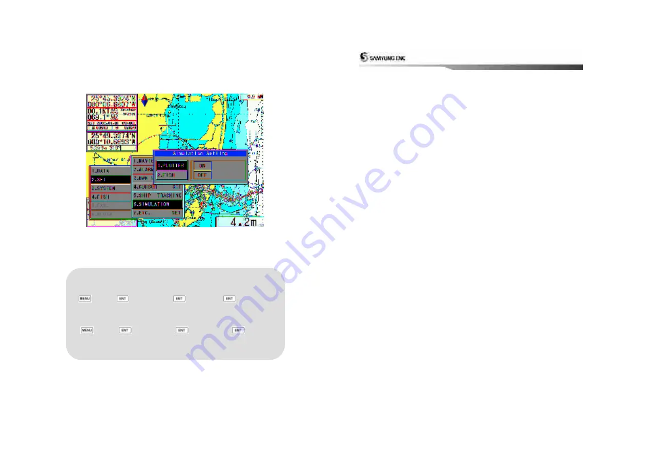
2.6 Simulation 
This enables the operators to display artificial data required for demonstration or testing purposes.


 Simulation Set 


 1. PLOTTER 


 [2.SET] 


 [6.SIMULATION] 


 [1.PLOTTER] 


(Whenever press 1.PLOTTER, ON/OFF selected.)   


 Fish-finder Simulation Set 


 [2.SET] 


 [6.SIMULATION] 


 [2.FISHFINDER] 


(Whenever press 2.Fishfinder, ON/OFF selected.) 


86 


2.7 Miscellaneous Set 
User can set up many additional functions on SYSTEM and Plotter. 


Summary of Contents for SGP-330

Page 1: ...andard Components 10 3 Device Display 12 1 Main Unit 13 2 Remote Controller Button 15 3 Power ON OFF 16 4 Menu Composition 17 5 Plotter Display 18 4 Operating Instruction 23 1 Data 24 1 1 Track Data 24 1 2 Mark Data 32 1 3 User Coast Line 40 1 4 Waypoint Data 46 1 5 Route Data 53 1 6 Disc Format 55 1 7 The Seabed Symbols 56 1 8 Software Update 57 2 Set Up 58 2 1 Navigation Set Up 58 2 2 Alarm func...

Page 2: ...Latitude Longitude Height In this positioning It s required 4 satellites to make the position 2D Positioning is to using Vessel Ship which is used only Latitude Longitude without height In case of 2D positioning It s required only 3 satellites to receive signal then time zone for positioning will be extended GPS gives more accurate positioning result always due to receiving signal from satellites ...

Page 3: ...Antenna Receiver DGPS Antenna Receiver Beacon Receiver Main Unit Features Functions Standard Components 2 FEATURES 6 1 GPS Antenna Receiver GPS Antenna Type All weather Micro strip patch antenna Power Supply Receiver Module Size Weight 102 x 65mm 150mm mounting bar 0 2kg ...

Page 4: ...tible with RGB input are available such as CRT and Flat type Monitor Resolution 640 x 480 pixels Power 8V to 32V DC Approx 5W Weight Dimension 217x143x36 760g 8 Navigation 1 Drawing Method Mercator s Scale Range 1 2 500 1 37 500 000 about 0 2nm 5 000nm Effective Display Range Less than Laititude 85 Menu Pull down Menu Coast Line Chart Display on the Tracking Screen Track Display Memory Interval TR...

Page 5: ...lectable Datum in worldwide Navigation data input output format In Output device available SAMYUNG FURUNO JRC NMEA0183 IEC 61162 10 3 Standard Components SGP 330 Plotter No Item Specification Q ty Remark 1 GPS Plotter SGP 330 1ea 2 GPS Antenna SAN 60 1ea 3 Antenna Cable RG 58C U 10 20m 4 DC Cable CVV SB 0 75 SQ MMx2C 3m 5 Spare Fuse 20mm 250V 2A 2ea 6 Install Material Piece and Earth Cable etc 1 L...

Page 6: ... 11 공 란 12 3 Device Display This Chapter explains Device and Display about SGP 330 Main Unit Remote Controller Button Power ON OFF Plotter Display 3 Device Display ...

Page 7: ...r coastline can be stored and Program can be updated through this SD Card USB HOST available later on It is a USB HOST terminal that can be connected with BACK UP external printer and other devices Available later on 14 Rear Panel RGB Output All monitors supportive with RGB input such as CRT flat monitor LCD are available Connecting to wire remote controller DATA in out Interface with other produc...

Page 8: ...Change Mark Type Mark Color Button Change mark Color Depth Button TBA F1 Button Option button for adding Function Dimmer LCD Dimmer Transparency Selecting day night mode in Screen 2 Remote Controller Button Sea Bottom Range Button later on 수심범위를 변경시 사용 MOB Button TBA 16 3 Power ON OFF Main Power ON OFF It is designed to keep ON OFF main power through Rocker Switch placed in rear panel of the Main ...

Page 9: ...pe 2 Set 1 Navigation Set 2 ALARM SET 3 Own Ship Set 4 Cursor Set 5 Ship Tracking 6 Simulation 7 ETC set 3 System 1 Satellite INFO 2 Screen Print 3 Keyboard Test 4 System Set 5 System Info 8 Program update 18 5 Plotter Display GPS Plotter Display 9 2 1 24 5 6 7 11 21 22 25 26 27 28 18 29 12 3 4 8 10 23 13 14 15 16 17 19 20 ...

Page 10: ... current MARK q ty 12 Cursor Press button to display on plotter screen 13 Latitude of Cursor Latitude of current cursor position 14 Longitude of Cursor Longitude of current cursor position 15 Distance Distance between current position and cursor 16 Bearing Bearing from own ship to current cursor 17 Trench Trench which is put a cursor 치한 지점의 해구도 18 Width of Display Real distance of width in display...

Page 11: ... 21 22 Day Night Mode in Plotter Display Press Open the menu such as Transparency Day Night mode ...

Page 12: ...n Total track to be saved is 20 000 points When it comes to be full memory delete point one by one REF When selected ON current track line is saved while selected OFF track line is not drawn and can not be saved Track Saving unit Set 1 Data 1 Track Data 1 Setup 2 Selection Whenever pressed Time Distance repeatedly selected Track Data Save ON OFF 1 Data 1 Track Data 1 Set 1 Save ON OFF changeably s...

Page 13: ...Data 1 Set 4 Distance Track Color Selection 1 Data 1 Track Data 1 Set 5 Color After selecting the wanted color press Track Line Thick selection 1 Data 1 Track Data 1 Set 6 Shape Whenever pressed thin thick repeatedly selected Time interval T Mark display 1 Data 1 Track Date 1 Set 7 T Mark Whenever pressed ON OFF repeatedly selected 26 1 1 2 Track Clear Use this function to erase the TRACK line of ...

Page 14: ...CALC 2 Color CALC After selecting the selected color press 28 1 1 4 Track Save Use this function to save TRACK DATA to selected device while vessel navigates Save Track in built in ROM 1 Data 1 Track Data 4 Save After input file name 0001 9999 press built in ROM and press Save track into SD card 1 Data 1 Track Data 4 Save After input file name 0001 9999 press SD and press ...

Page 15: ...ress 30 1 1 5 Track Load Use this function to load saved file from 1 1 4 Track Save and Display on the plotter screen Built in ROM Track Load 1 Data 1 Track Data 5 Load Built in ROM After selecting Geodetic Conversion press SD Card Track Load 1 Data 1 Track Data 5 Load SD Card After selecting the file to be loaded press Once you load the saved TRACK file any previous TRACK drawn on the screen will...

Page 16: ...fter selecting the file to be erased press after selecting YES Press 32 1 2 Mark Data 1 2 1 Mark Select Use this function to select which MARK type to show on the screen There are 21 unique MARK types REF 1 Shortcut key and button 2 After selecting Line Start or Line Continue mark move cursor on plotter screen and press to draw Line If you want to erase the line make the cursor overlap each MARK a...

Page 17: ...tion 2 Press Move cursor Press to input easier MARK can be input up to 10 000 points if you need to input more than 10 000 points it displays all mark points used Mark Append at own ship s position 1 Data 2 Mark Data 2 Append 1 Own ship s position Mark append to a certain Longitude Latitude 1 Data 2 Mark Data 2 Append 2 Lat Long After inputting Longitude value press after inputting latitude value ...

Page 18: ...a 2 mark Data 3 Clear 2 Ownship position Clears mark in color 1 Data 2 Mark data 3 clear 3 color clear after selecting the color press 36 REF Shortcut to clear the Mark On the plotter screen place on the mark to clear by using direction key and press Clear MARK in Lat Long 1 Data 2 Mark Data 3 Clear 4 Lat Lon After selecting Lat press after selecting Lon press ...

Page 19: ... in output terminal and to save 1 Data 2 Mark Data 4 save after inputting file name 0001 9999 press COM port and press 38 1 2 5 MARK Load 1 2 4 Display a mark on the plotter screen after recalling a saved file from a storage device LOAD MARK STORED in built in ROM 1 Data 2 Mark data 5 Load Built in ROM after select changing Geodetic press LOAD MARK stored in SD CARD 1 Data 2 Mark data 5 Load SD CA...

Page 20: ...6 Erase Built in ROM after select YES press SD CARD ERASE 1 Data 2 Mark data 6 Erase SD CARD after select the file press after select YES press 40 1 3 User Coast Line 1 3 1 Coast Line Mark This function is used to display a coastal line drawn by a user onto the plotter screen In the ON setting the coastal line drawing is displayed COASTAL LINE ON OFF 1 data 3 User s Line 1 Display Select ON OFF Pr...

Page 21: ... desired position and Move the cursor the connecting position and press How to input the Characters Name of place 1 DATA 3 USER S LINE 2 DRAWING line drawing Dimmer button Input the Character using direction center button and press 42 REF 1 Line color can be changed by pressing button How to erase coastal line 1 DATA 3 USER S LINE 2 DRAWING after moving the cursor to the starting point to erase pr...

Page 22: ...e by sending to another device using external in out terminal 1 Data 1 Track Data 4 Storage After input file name 0001 9999 press COM PORT and press 44 1 3 4 Coastal Line Load 1 3 3 Display a mark in a Plotter Screen after recalling a saved file from a storage device Coastal Line Load from built in ROM 1 Data 3 User Coastal Line 4 Load Built in ROM After selecting Geodetic conversion Press Coastal...

Page 23: ...ilt in ROM 1 Data 3 USER COASTAL LINE 5 ERASE Built in ROM COASTAL LINE ERASE from SD CARD 1 Data 3 USER COASTAL LINE 5 Erase SD CARD After selecting the file to erase press 46 1 4 Waypoint Data 1 4 1 Waypoint Mark Use this function to place a waypoint onto a Plotter screen ON the waypoint is placed on the screen Waypoint display ON OFF 1 Data 4 Waypoint Data 1 Display After selecting ON OFF press...

Page 24: ...point On Plotter Screen Own ship s position is registered On Plotter Screen move cursor and select waypoint then cursor position is registered 48 REF On the waypoint edit window button is moved in 10 units button is moved 10 units How to erase waypoint data registered On the waypoint edit window Select the blank number Converted to Center After Selecting the number to erase using direction key and...

Page 25: ...st format first Refer to 1 6 Disk Format WAYPOINT STORAGE in Built in ROM 1 Data 4 Waypoint Data 3 Storage after input file name 0001 9999 press Built in ROM and press WAYPOINT STORAGE in SD CARD 1 Data 4 Waypoint Data 3 Storage after input file name 0001 9999 press SD CARD 50 Waypoint Storage by sending Data It is a function to save by sending to another device using external in out terminal 1 Da...

Page 26: ...CALL C USER CARD select file name wishing to recall Please be advised that any currently displayed waypoints are deleted when the stored waypoint is recalled Caution 52 1 4 5 WAYPOINT ERASE 1 4 3 Deleted a coastal line file from a storage tool Must be careful to command this erase due to no recover the file Waypoint Erase on ROM 1 Data 4 Waypoint Data 5 Erase ROM Select YES Waypoint Erase on C Use...

Page 27: ...s available To cancel recording a waypoint to the route move the cursor to the waypoint number to be canceled and then press 54 REF 1 moving as per 10 ea and is moving 10 ea on Route Edit window 2 In case of navigating to jump up a certain of the waypoint in a navigate route move the cursor to the required number and then press J Jump character is shown in beside of the waypoint number and it can ...

Page 28: ...s able to read user card is defective 3 No insulted user card How to format a disk 1 DATA 6 DISK FORMAT 1 SD CARD Takes 5 min around When formatting a card or disc all data is deleted and it cannot be recovered CAUTION 56 1 7 The Seabed Symbols Use this function to place bottom feature symbols on the plotter chart To see the detail of the seabed symbols 1 DATA 7 SEABED TYPE Move to next page by ...

Page 29: ... the vessel navigates between two voluntary waypoints is registered on 1 4 2 WAYPOINT EDIT or on vessel s present position Waypoint Navigation Set 2 SET 1 NAVIGATION SET 1 WAYPOINT NAVIGATION Select The start Waypoint number 0000 number shows own ship s position Select The arrival Waypoint number The red line is shown from a starting Waypoint to an arrival Waypoint The Lat Lon approach speed direc...

Page 30: ... ROUTE EDIT ROUTE NAVIGATION SET 2 SET 1 NAVIGATION SET 2 ROUTE NAVIGATION SET Select registered route no 01 20 press The Lat Lon approach speed direction distance and total navigation time are shown in a bottom left of the plotter screen once route navigation set NAVIGATION BY ROUTE in reverse order Select route no 01 20 press R is displayed next to route number and set Navigation By Route In Rev...

Page 31: ... 61 62 To cancel Route Navigation Press on remote controller Refer to 2 1 4 NAVIGATION CLEAR ...

Page 32: ... a cursor to waypoint Register first route waypoint no 9980 Move a cursor next waypoint Register second route waypoint 9981 Able to register max 20 pcs Disappear cursor and cursor line Route Navigation Clear Press quick button Refer to 2 1 4 EXIT WPT RTE ANCHOR 64 ...

Page 33: ...ge This function is using with 2 2 3 ANCHORAGE ALARM ANCHOR set 2 SET 1 NAVIGATION SET 3 ANCHOR Own vessel s position is set as anchor position The Lat Lon approach speed direction and distance are shown in a bottom left of the plotter screen once route navigation set 66 To cancel anchor position set Press on remote controller Refer to 2 1 4 NAVIGATION CLEAR ...

Page 34: ...ge when 2 2 3 ANCHOR ALARM is ON 68 2 1 4 EXIT WPT RTE ANCHOR This function cancel Waypoint Route Navigation Anchor Position Set EXIT WPT RTE ANCHOR 2 SET 1 NAVIGATION SET 4 EXIT WPT RTE ANCHOR For quick way to EXIT WPT RTE ANCHOR Press on remote controller ...

Page 35: ...ress ON OFF repeatedly selected When selecting ON use the numbers to input Arrival Alarming Range 0 01 9 99 When Arrival Alarm is on press on remote controller to cancel 70 2 2 2 Cross Track Error Alarm XTE While using in the Navigation Mode this function sounds an alarm to alert the operator of an off course condition REF The XTE range is indicated with a blue line the window in the bottom shows ...

Page 36: ...ed when the vessel drifts out of the anchor set range due to tide and weather Anchorage Alarm ON OFF 2 SET 2 ALARM SET 3 ANCHOR ALARM Whenever press ON OFF repeatedly selected Select ON and use the numbers to input Anchorage Alarm Range 0 01 9 99 Anchorage range is indicated by a red circle ...

Page 37: ...Whenever press ON OFF repeatedly selected 74 2 2 5 Water Depth Alarm This function is used to alert the operator when it senses any specific water depth within the preset alarm range Sensor input is through the transducers It is user selectable from 1m 999m Water Depth Alarm ON OFF 2 SET 2 ALARM SET 5 WATER DEPTH ALARM Whenever press ON OFF repeatedly selected Select ON input depth wishing to set ...

Page 38: ...eed small fishing boats 3 5 6 9 SMOOTHING SET The set up differs from the vessel type The higher the value entered the more stable it is 2 SET 3 SHIP SET 4 SMOOTHING SET Input position smoothing value 1 9 Input speed smoothing value 0 399 Input bearing smoothing value 0 99 LAT LON CORRECTION If any value error of the current position the log lat can be corrected per second minute with this functio...

Page 39: ... Whenever press SMALL MID LARGE selected in order 차적으로 선택됨 HEADING COLOR SET 2 SET 3 SHIP SET 8 HEADING COLOR Whenever press RED GREEN BLUE selected in order HEADING SHAPE select 2 SET 3 SHIP SET 9 HEADING SHAPE Whenever press Thin Thick repeatedly selected ...

Page 40: ... display CURSOR SIZE 2 SET 4 CURSOR SET 1 CURSOR SIZE Whenever press SMALL BIG repeatedly selected CURSOR COLOR 2 SET 4 CURSOR SET 2 CURSOR COLOR Whenever press BLUE RED GREEN selected in order 80 CURSOR SHAPE 2 SET 4 CURSOR SET 3 CURSOR SHAPR Whenever press THIN THICK repeatedly selected ...

Page 41: ...y selected 82 2 5 Ship Tracking Has no this function 2 5 1 Ship Tracking To track a vessel s position and waypoint by inputting vessel ID to vessel If you are willing to make this function is ON it should be set 2 5 2 SHIP TRACK EDIT first REF A communication equipment need for ship tracking SRG 2050D SRG 1150D 1250D DSC VHF STR 580D 680D 6000A SHIP TRACKING ON OFF 2 SET 5 SHIP TRACKING 1 RUN ON ...

Page 42: ...t 2 SET 5 SHIP TRACKING 2 EDIT Choose tracking no from 01 to 20 Choose tracking ON OFF Input vessel ID 9 digits Input vessel name Use direction and CTR button 84 REF Input 000000000 to delete a vessel ID and then press Input a blank to delete a vessel name and then press For call interval set press wishing interval sec and then press ...

Page 43: ... testing purposes Simulation Set 1 PLOTTER 2 SET 6 SIMULATION 1 PLOTTER Whenever press 1 PLOTTER ON OFF selected Fish finder Simulation Set 2 SET 6 SIMULATION 2 FISHFINDER Whenever press 2 Fishfinder ON OFF selected 86 2 7 Miscellaneous Set User can set up many additional functions on SYSTEM and Plotter ...

Page 44: ...tic North This is Magnetic Bearing Deviation and Magnetic North is meant for magnetic compass s north 2 SET 7 ETC SET 2 MAGNETIC VAR Input value of magnetic north deviation Whenever press repeatedly select NM KM MM CABLE DISPLAY 2 SET 7 ETC SET 4 CABLE DISPLAY Whenever press ON OFF repeatedly selected COURSE UP SET To set chart direction 2 SET 7 ETC SET 3 COURSE UP SET Whenever Auto Course North E...

Page 45: ...o display and then press Display as POSITION PRINT SET To print out vessel position speed heading by time interval 2 SET 7 ETC SET 7 POSITION PRINT Input time interval and press PASSWORD SET Initial set is 0000 2 SET 7 ETC SET 9 PASSWORD SET Input new password 4 Digits Re input new password Confirm by press SPECIAL SHIP SET For wastes carrier vessel it is able to print out time and position of val...

Page 46: ...In case of no receiving GPS signal 3 SYSTEM 1 SATELLITE INFO 1 INITIAL POS Input Lat Value and press Input Log Value and press 92 Date Time Set User can set up the information on the date and time In case of no receiving of GPS signal 3 SYSTEM 1 SATELLITE INFO 2 DATE TIME SET Input yy mm dd and press Input Time Min Sec and press Local Time Set User can set up the information on the weather and tim...

Page 47: ...TELLITE INOF 7 ANTENNA HEIGHT Height set Geodetic Datum Set Choose a world standard WGS 84 for datum 3 SYSTEM 1 SATELLITE INFO 8 Datum Select Choose datum and press 94 3 2 Print Out USB TBA To printout a current plotter screen by using printer How to printout 3 SYSTEM 2 SCREEN PRINT 1 Start printing Printer Select Only available to use a printer which is supported by HP PCL Sea Color Print If choo...

Page 48: ... 95 96 3 3 Keyboard Test Users can make a self test to see if the remote works okay How to test keyboard 3 SYSTEM 3 KEYBOARD TEST Check button s reversal by pressing each button ...

Page 49: ...l User can directly use the data received from the internal GPS linked to this SYSTEM External User can use the data coming out from other GPS equipment to input to this system Input PORT Set Data input port of SYSTEM can be set up 3 SYSTEM 4 SYSTEM SET 1 INPUT PORT SET Whenever press Internal External selected repeatedly ...

Page 50: ...lect time sec interval When connect with Samyung Auto Pilot System Put a cursor on PLT at output sentence PLT check PLT Sentence is designed to work normally when it is connected with SAMYUNG autopilot and selected 100 AIS SET Run Stop This is to receive the information on ship name MMSI ship speed from AIS mounted ships and display the information on the screen 3 SYSTEM 4 SYSTEM SET 3 AIS SET 1 R...

Page 51: ...F Same set as above for 4 Target Color 2 8 Target Color 6 The target which not belonging to target color 2 to 6 is able to set by 9 ETC COLOR with color choosing only AIS Target Color Set Set a color by MID Marine Identification No or Country Code 3 SYSTEM 4 SYSTEM SET 3 AIS SET 3 TARGET COLOR 1 Input MID Select color ...

Page 52: ... voyage COG Current course of ship under voyage 104 Details on AIS Mounted Ship NAME Ship Name C SIGN Call Sign MMSI Maritime ID IMO NO IMO number DRAUGHT Draught S TYPE Ship Type DEST Destination NAV Current Navigational Status LAT Latitude LON Current Longitude of Ship SOG Speed COG Course HDG Heading ROT Rotation GNSS Antenna Position GPS position installed on board ...

Page 53: ...ct BLANK Level LANGUAGE SET 3 SYSTEM 4 SYSTEM SET 6 LANGUAGE SET Whenever press Korea English Russian China Taiwan selected in sequence And then power off Rebooting 106 3 5 System Information Users can display the system information such as LCD Plotter Model Program Chart PIC Version LCD MODE Set Set as Sharp 3 SYSTEM 5 SYSTEM INFO 1 LCD MODE Whenever press Sharp PVI 1 PVI 5 selected in order PLOT...

Page 54: ...t the rear of the unit is properly connected Cables Check the condition of all cables Replace any damaged cables with new ones Ground Terminal and cable Check the condition of the ground terminal If it is rusted or defective replace it with a new one or clean it Also make sure the connection status of the ground cable to the vessels bonding system Cleanliness Remove out the dust from LCD by using ...

Page 55: ...ars Screen color is sometimes changing 1 Check LCD contact point RGB OUT connector 2 Clean contact point for LCD connector RGB OUT connector Position coordinator is inaccurate 1 Check for selection of KOREA at Geodetic device 2 Set the value 0 if compensating function for latitude and longitude is set The value of the speed of the ship is inaccurate 1 Adjust the smoothing function to make it high ...

Reviews: