


12 _ Removal and Reassembly
Part
Figure
Description
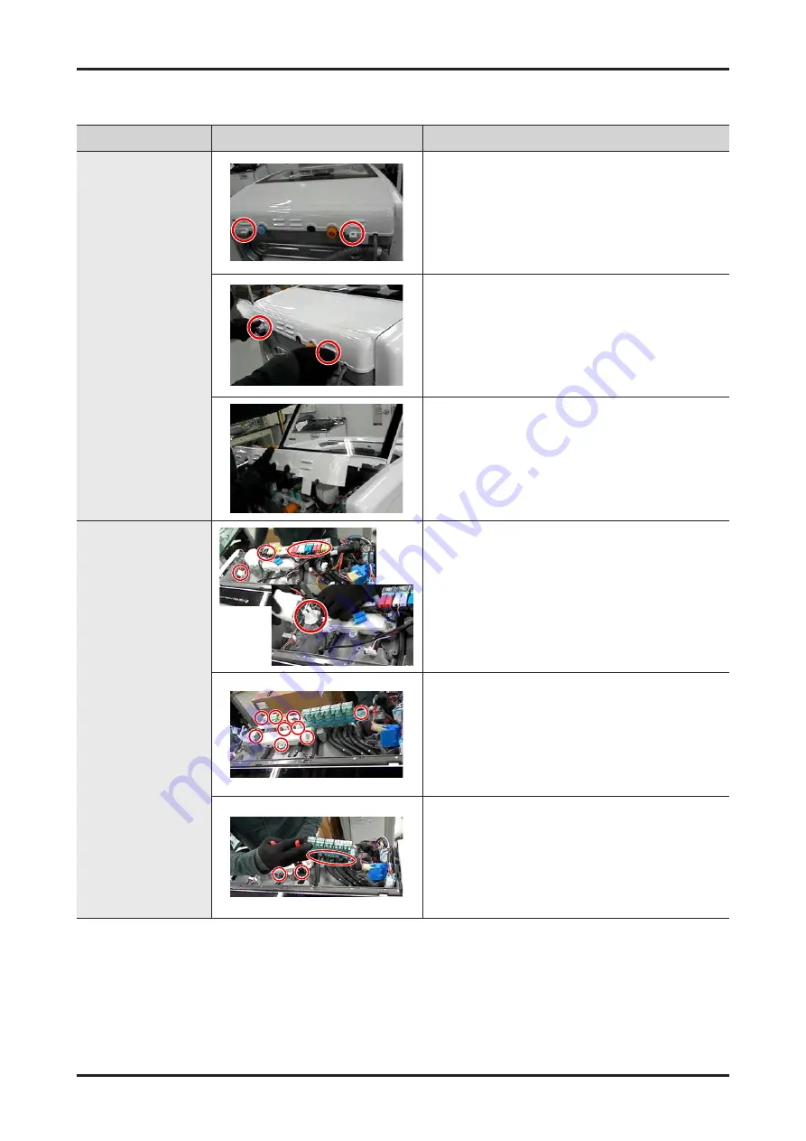
Disassembling and
Repairing the
Cover-T.C
1. Remove the 2 screws, which are at the back,
fixing the COVER-TC
2. Grab the hook and lift it up.
3. It is easily disassembled when lifted at the
same time as LID-T.C
Disassembling and
Repairing the Water
Supply Valve
1. Disconnect the connector connected to the
Waver valve.Open the lid and remove the
connector connected to EMI-FILTER.
2. Remove 9 SCREW
3. Use the tool to remove 6 points of the clip and
separate the water valve


