


8 _ Features and Specifications
2-3. CoMPARINg SPeCIFICATIoNS WITH exISTINg MoDeLS
grade
WF5000HA
yuKoN BeTTeR
Model Name
WF42H5000AW
WF431ABW
WF431ABP
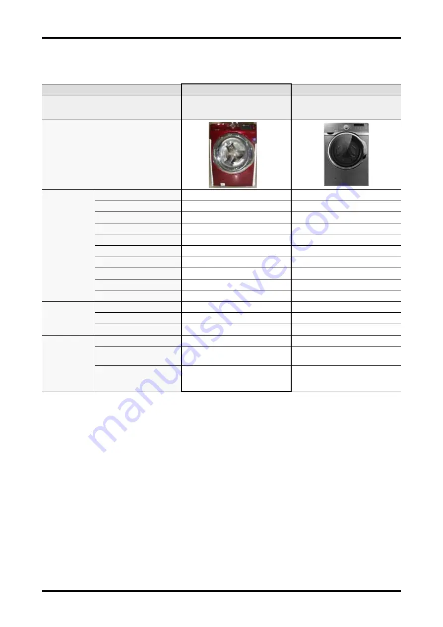
Image
Main Spec
Capacity (cu.ft / IEC)
4.2cu.ft
4.5cu.ft
Motor type
DD Motor
DD Motor
Max RPM
1,200
1300
VRT
Yes
Yes
heater(900w)
Yes
Yes
Diamond Drum
Yes
Yes
Washing Cycle#
9
13
Delay wash
24hrs
24hrs
Tilted Drum
10°
10°
Sound Pressure
Ave 58dBA
Ave 56.3dBA
Target
performanece
MEF
3.2
3.2
WCF
2.9
2.99
kWh/year
93 kWh/year
95 kWh/year
Design
control Display
LED
G.LED
Frame Color
Refined-wine
W: White
P: Stainless platium
Dimension
27.0X 33.0 X 38.7"
27 X 32.3 X 38.7"


