background image

Removal and Reassembly _ 13

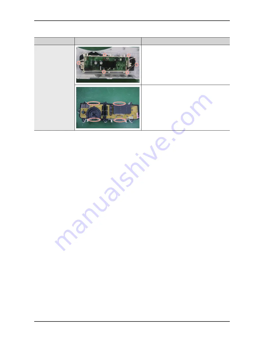
Part

figure

Description

separating the 

Cover_Top and 

Panel-Control 

(Check main-PCb 

and sub-PCb)

7.  Remove the 6 screws and separate the ASSY 

PCB.(Separate the ASSY KNOB ENCODER at 

first)

8.  Disassemble MAIN-PCB and SUB-PCB from the 

ASSY PCB by pressing on the hook.

Summary of Contents for WF365BTB series

Page 1: ...363BTB WF365BTB Model Code WF361BVBEWR A2 WF363BTBEUF A2 WF365BTBGWR A2 Refer to the service manual in the GSPN see the rear cover for the more information 1 Safety Instructions 2 Features and Specifi...

Page 2: ...3 1 Tools for disassembly and reassembly 9 3 2 Standard disassembly drawings 10 4 Troubleshooting 21 4 1 Error modes 21 4 2 Corrective actions for each error code 25 5 PCB diagram 33 5 1 Main PCB 33 5...

Page 3: ...isconnect the power plug before servicing 4 Failing to do so may result in a risk of electric shock Do not allow consumers to connect several appliances to a single power outlet at the same time 4 The...

Page 4: ...ot press a control button using a sharp tool or object 4 This may result in electric shock or damage to the product WHILE SERVICING When wiring a harness make sure to seal it completely so no liquid c...

Page 5: ...kage AFTER SERVICING Check the wiring 4 Ensure that no wire touches a rotating part or a sharpened part of the electrical harness Check for any water leakage 4 Perform a test run for the washing machi...

Page 6: ...utlet and measure the insulation resistance between the power plug and the grounding wire of the washing machine The value must be greater than 10M when measured with a 500V DC Megger Check whether th...

Page 7: ...Direct Drive Inverter Motor The power to handle anything Our direct drive inverter motor delivers power right to the washer tub from a variable speed reversible motor A direct drive motor generates a...

Page 8: ...verall 38 7 98 4 cm B Width 27 68 6 cm C Depth With Door Open 90 50 8 129 cm D Depth 31 5 80 cm WATER PRESSURE 20 116 psi 137 kPa 800 kPa WEIGHT 174 lbs 79 kg CAPACITY 3 6 cu ft POWER CONSUMPTION WASH...

Page 9: ...l Delay Wash 19 hrs delay wash 19 hrs delay wash 19 hrs delay wash 19 hrs delay wash Garment Yes Yes Yes Yes Tilted Drum 10 degree 10 degree 10 degree 10 degree Target Performance MEF Above 3 0 Above...

Page 10: ...ANNER Wrench DC60 40146A Default CAP FIXER DC67 00307A 5EA Default ASSY HOSE WATER C DC97 15648A Default ASSY HOSE WATER H DC97 15648B Default HOSE HANGER DC62 10278A Default MANUAL USER DC68 02832J D...

Page 11: ...5 Motor 2 Balance 9 13mm Shock Absorber 2 holes each in left right Damper 2 Damper friction 2 19mm Pulley 1 Double ended spanner 10mm 13mm 19mm Replaced by box driver Leg Vice pliers A Tool for protec...

Page 12: ...removing the rotor requires a lot of strength due to the magnetic force of the Rotor and it may come off suddenly your hand or arm may be injured by the edge of the Stator or Frame Therefore take prec...

Page 13: ...not completely release the nut Pull the Heater forward after releasing the nut If the Heater is damaged it may cause a problem Therefore unfasten the nut using spanner or wrench manually without using...

Page 14: ...le the COVER TOP by sliding it backwards and remove the 4 screws on the PANEL CONTROL Separate Button 3 Press the Separate button to separate the ASSY DRAWER 4 Disassemble the HOUSING DRAWER from the...

Page 15: ...cription Separating the Cover_Top and Panel Control Check Main PCB and Sub PCB 7 Remove the 6 screws and separate the ASSY PCB Separate the ASSY KNOB ENCODER at first 8 Disassemble MAIN PCB and SUB PC...

Page 16: ...ng it up slightly 3 Remove the 15 screws fixing the HOLDER GLASS including the 2 blue screws holding the LEVER DOOR 4 Disassemble the HOLDER GLASS from COVER DOOR 5 Remove the 8 screws to separate the...

Page 17: ...separate the DOOR LOCK S W 3 Remove the 4 screws at the top of FRAME FRONT To assemble hook the FRAME FRONT onto the BOTTOM PALTE and then insert the assembly hook into the hole 4 Push the lever and p...

Page 18: ...sembling and Repairing the Water Level Sensor 1 Separate the wire connected the SENSOR PRESSURE 2 Adjust the plastic clip of pressure sensor between two nose of plier then grip and pull the plastic cl...

Page 19: ...te the Clamp of the hose connected to the PUMP and then pull the HOSE AIR 4 Separate the Clamp of the hose connected to the PUMP and then pull the HOSE DRAIN 5 Separate the wire connected to the PUMP...

Page 20: ...ews fixing GUIDE WIRE 6 screws fixing FRAME PLATE U 2 Remove the 4 bolts fixing WEIGHT BALANCER and then pull it towards with caution 3 Remove the 4 bolts fixing DAMPER to take ASSY TUB out 4 Remove a...

Page 21: ...mbly _ 19 Part Figure Description Disassembling the Tub 6 Lift the ASSY TUB with two people carefully with holding SPRING HANGER 7 Remove the M10 bolt from the middle of the TUB and separate the TUB F...

Page 22: ...remove 6 M10 bolts from the upper ASSY DRUM disassemble the ASSY FLANGE SHAFT 2 Remove 12 screws from the outer sides and then remove the two upper and lower BALL BALANCERS 3 Remove 3 screws from the...

Page 23: ...e is generated due to too much laundry etc bE This occurs due to erroneous operating signals from the motor hall sensor The IPM terminal of the main PBA is not connected The DD motor cover is out of p...

Page 24: ...that a power failure has occurred Communication Error The signals between the sub and main PBAs are not sensed because of commuication error Check the connector connections between the sub and main P...

Page 25: ...he heater has no error this occurs because of a PBA relay malfunction This error occurs when the red temperature sensor at the center of the dry heater operates at a temperature higher than 145 C Corr...

Page 26: ...disconnected If the water level sensor operates without water because the water is frozen or for any other reason and the temperature sensor engaged at the bottom to prevent overheating for the washi...

Page 27: ...eck it after the water level sensor and the connector are connected Frequency Approx 26 4 KHz with no load Washing Motor Error and Hall Sensor Error Continued 3E E3 bE Washing motor fault Washing moto...

Page 28: ...nce of No 1 and No 4 of the wire pin on the side of the TACHO SENSOR Resistance Approximately 40 to 45 Normal THREE PHASE MOTOR Measure the Resistance of No 2 and No 3 of the wire pin on the side of t...

Page 29: ...al in the water supply valve diaphragm Drain Error nd Drain pump fault Freezing in the winter season Foreign materials in the drain pump Main PCB fault Check whether the revolutions of the drain pump...

Page 30: ...A button other than the Power button is continually pressed Main PCB relay fault Check whether either the Power switch or a tact switch is continually pressed Check whether the service PBA holding sc...

Page 31: ...is on That is check the door switch when the power button is turned on and no operating key is pressed dL LO TYPE 2 The resistance across No 3 and No 5 of the DOOR LOCK SWITCH must be approximately 94...

Page 32: ...as a functional error replace it Check the hose This error occurs if it is torn or has a hole This error occurs if water is frozen in the winter season Use hair dryer to defrost hose Consider relocati...

Page 33: ...Unbalance Error dc Motor hall sensor fault Caused by the laundry contents Check the type of laundry Check whether it may cause an unbalanced situation Educate the consumer in this case is to press pa...

Page 34: ...32 _ Troubleshooting MEMO...

Page 35: ...models 4 BD1 Making DC Voltage It works to Change the AC to the DC 5 IC9 Switching IC Making a stable DC 6 LVT1 Trans Circuit Chopping the DC Link Location Part No Function Description 7 IC1 2 Regulat...

Page 36: ...ication Port Rx 3 Reset Signal Output 4 5V 5 Ground 6 15V 7 Empty Pin 8 Water Level Sensing CN6 1 Ground 2 Rx_From_Flash_ Writing 3 Tx_To_Flash_Writing 4 Mode 5 Sub_Reset 6 5V CN5 1 Main Valve 2 Hot V...

Page 37: ...slkXX v G kYW l k v p k G u v p w v k k_ slkXW ky ly hzoly hzoly il ly nvvk o o o W X v v v v v z XX qwY ju qw qw yZ z yZ qwX qwZ qw ju v ky ly v o t X v v v ky ly nvvk Z X Y Z X Y Y X Y X v v slkY v...

Page 38: ...Document can not be used without Samsung s authorization CN3 1 Thermistor 2 Ground 3 Water Level Sensor Signal In 4 Water Level Sensor Signal Out CN2 1 Communication Port Tx 2 Communication Port Rx 3...

Page 39: ...ram 6 1 Wiring diagram This Document can not be used without Samsung s authorization n Reference Information BLK BLACK BLU BLUE GRN GREEN GRY GRAY NTR NATURAL ORG ORANGE PNK PINK RED RED SKYBLU SKYBLU...

Page 40: ...6 P 7 N A 0 _ 0 P 6 N A 1 _ 0 P 5 N A 2 _ 0 P 4 N A 3 _ 0 P O E R T 3 N A 4 _ 0 P 2 N A 5 _ 0 P 0 A D 1 N A 6 _ 0 P P5_6 P0_7 AN0 DA1 P3_2 P1_0 AN8 LVCMP1 KI0 P3_0 P1_1 AN9 LVCMP2 KI1 P4_2 VREF P1_2...

Page 41: ...1 16MHz 2 3 1 7 W S 5 0 0 6 N W 3 B V 2 1 A m 0 5 2 1 5 0 0 6 N W 3 B 6 W S 2 1 5 W S 2 1 4 W S 2 1 3 W S 2 1 KEY1 CGND 2 3 R K 0 1 J W 5 2 1 0 2 1 LED0 LED1 LED2 LED3 LED4 LED5 LED6 DIGIT0 DIGIT1 DIG...

Page 42: ...A D LED Chrome Hair Line 4 G LED Metal Chrome 5 G LED Chrome 6 G LED Chrome Hairline 7 Touch LED Chrome 8 LCD Chrome 9 LCD Chrome Hairline Capacity 3 6 cu ft Color Code WR NEAT WHITE UF HAZE BLUE Feat...

Page 43: ...ungcsportal com North Latin America gspn3 samsungcsportal com China china samsungportal com This Service Manual is a property of Samsung Electronics Co Ltd Any unauthorized use of Manual can be punish...

Reviews: