Samsung WDR-SV4 User Manual Download Page 18

COLOR CCD CAMERA

User’s Manual

37

COLOR CCD CAMERA

User’s Manual

36

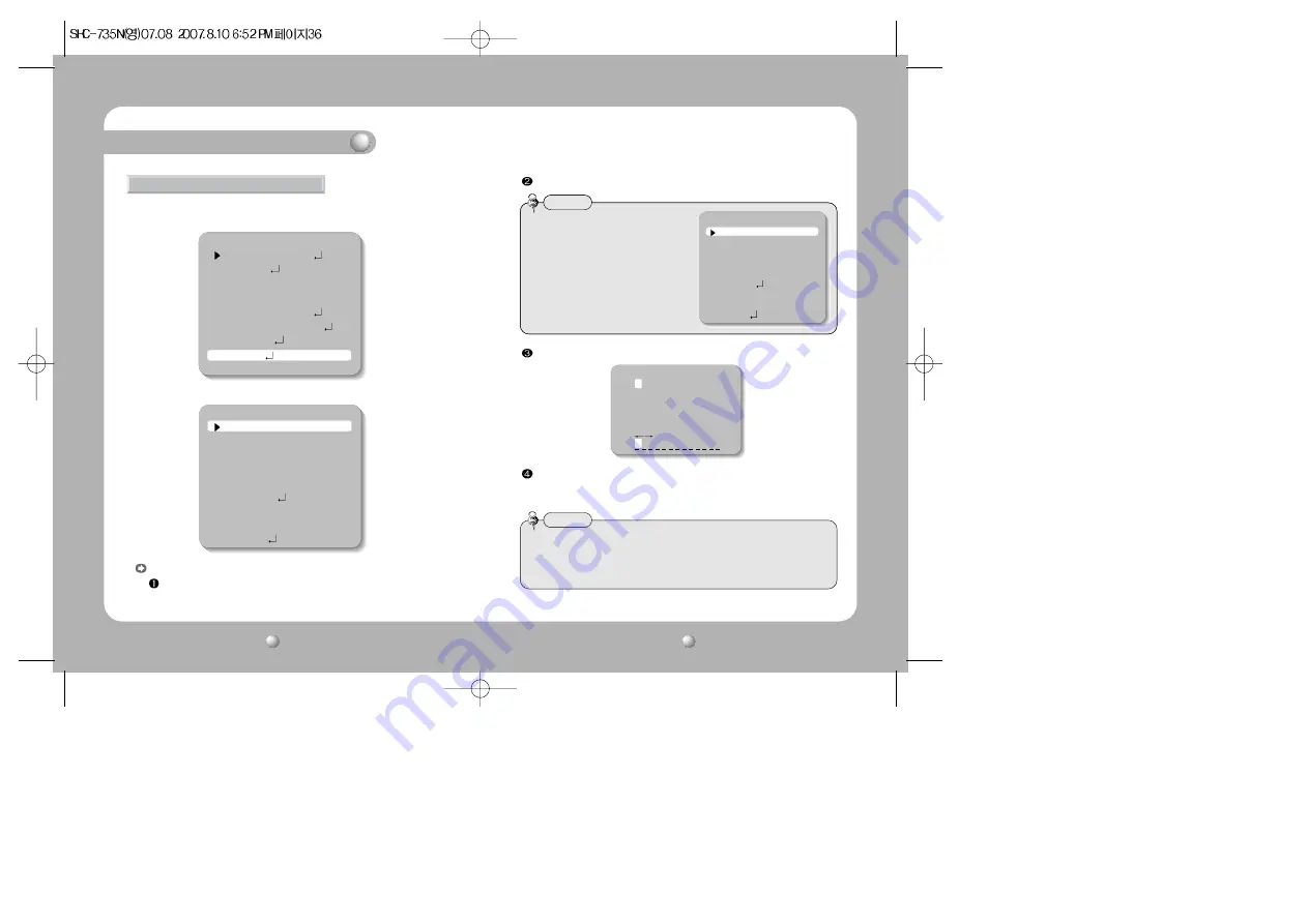
Press the SET button.

Use the 4 direction buttons to move to a desired letter and select the letter by
pressing the SET button. Repeat this to enter multiple letters. 
You can enter up to 15 letters.

CAM TITLE : If you enter a title, the title will appear on the monitor.

If the SPECIAL menu screen is displayed, use the Up and Down buttons so
that the arrow indicates ‘CAM TITLE’.

Set it to ‘ON’ by using the Left and Right buttons. 

1. When the SETUP menu screen is displayed, select ‘SPECIAL’ by using the Up and

Down buttons so that the arrow indicates ‘SPECIAL’.

2. Select a desired mode using the Up and Down buttons.

SPECIAL

MAIN SETUP

1.LENS

DC

2.EXPOSURE
3.WHITE BAL

ATW

4.BACKLIGHT

OFF

5.SSNR

ON

6.DAY/NIGHT

AUTO

7.IMAGE ADJ
8.SPECIAL
9.EXIT

SPECIAL

1. CAM TITLE

OFF

2. SYNC

INT

3. MOTION DET

OFF

4. PRIVACY

OFF

5. DIS

OFF

6. COMM ADJ
7. LANGUAGE

ENGLISH

8. RESET
9. RETURN

• When the CAM TITLE menu is ‘OFF’, no

title will be displayed on the monitor
screen even if you enter one.

Notes

• When the CAM TITLE menu is ‘OFF’, no

title will be displayed on the monitor
screen even if you enter one.

Notes

• If you move the cursor to CLR and press the SET button, all the letters are

deleted. To edit a letter, change the cursor to the bottom left arrow and press the
SET button. Move the cursor over the letter to be edited, move the cursor to the
letter to be inserted and then press the SET button.

Notes

SPECIAL

1. CAM TITLE

OFF

2. SYNC

INT

3. MOTION DET

OFF

4. PRIVACY

OFF

5. DIS

OFF

6. COMM ADJ
7. LANGUAGE

ENGLISH

8. RESET
9. RETURN

How to Use the Camera

Camera ID

A B C D E F G H I J K L M

N O P Q R S T U V W X Y Z

a b c d e f g h i j k l m

n o p q r s t u v w x y z

- . 1 2 3 4 5 6 7 8 9

CLR POS END

Summary of Contents for WDR-SV4

Page 1: ...Before attempting to connect or operate this product please read these instructions carefully and save this manual for future use Supreme Resolution WDR Camera WDR SV4 SHC 735 User s Manual ENGLISH ...

Page 2: ...a RS 485 Interface 6 Precautions 8 Components and Accessories 10 Overview 11 11 12 13 14 Installation Procedures 15 19 20 21 15 How to Use the Camera 22 22 23 24 26 28 29 31 32 34 36 40 Troubleshooting 41 Specifications 43 Function Menu Structure How to Set up the Functions LENS EXPOSURE WHITE BALANCE BACKLIGHT SSNR DAY NIGHT IMAGE ADJ SPECIAL EXIT Contents ...

Page 3: ...PAL English French German Spanish Italian Chinese Wide Dynamic Range WDR By adopting a proprietary SV IV DSP chip the camera delivers clear high quality pictures even in backlight by increasing exposure in dark areas while decreasing it in bright areas a corrected image with clear details results SSNR Samsung Super Noise Reduction Function The high performance SV IV DSP chip dramatically reduces t...

Page 4: ... lens is the most important component of the camera Be careful not to smear it with fingerprints Do not drop the camera or subject it to physical shock May cause a product malfunction Never keep the camera face to strong light directly May damage the CCD Do not expose the camera to radioactivity Radioactivity exposure may damage the CCD Do not expose the camera to rain or other types of liquids Wi...

Page 5: ... Lens Connector Plug 3 C Mount Adapter 4 Instruction Manual Front View Overview Components and Accessories Tripod Mounting Bracket Screw Hole Used to fix the Tripod Mounting Bracket to the top of the camera C Mount Lens Adapter Install this adapter to use a C Mount Lens Back Focus Control Lever Adjust focus by this Back Focus Lever ...

Page 6: ...on a bracket or tripod The screw sizes for this hole are as follows 1 4 20 UNC 20 THREAD L 4 5mm 0 2mm ISO standard or 0 197 ASA standard L You can separate the Tripod Mounting Bracket and install it on the top or bottom of the camera Make sure to use the Tripod Mounting Bracket when fixing the camera to a bracket or tripod Otherwise the camera may not be secure or the internal circuitry of the ca...

Page 7: ...t Button Used to move the cursor left or right in the menu screen or to change the value of the selected item D N Input Port You can switch to Day Night Mode by connecting an external signal to this port MD Output Port Motion detection signals are output through this port RS 485 Control Port You can control SETUP MENU through this port by using external controllers like a Remote controller that RS...

Page 8: ...d When Using a CS Mount Lens Remove the protective glass cover at the front of this product and turn the CS Mount Lens clockwise to install it And set focus of camera using Back Focus Control Lever of camera side after combining CS Mount lens When Using C CS Mount Lens C Mount Lens 10mm or less CS Mount Lens 5mm or less 3 Remove the cover of the auto iris lens connector plug and solder the lens ca...

Page 9: ...cted before making any connections Turn the 75 Hi Z switches of interim display devices to the Hi Z position and the switches of any final device to the 75Ω position CCD Camera CCD Camera Intermediate End monitor Monitor When Using a C Mount Lens 1 Remove the protective glass cover at the front of this product and turn the C Mount Adapter clockwise to install it 2 Turn the C Mount lens clockwise t...

Page 10: ... to the DVR or System Controller RS 485 Communication establishment initial value 485 Control Board Connection Port RS 485 Control Port CONNECTION TERMINAL TRX 485 CONNECTION TERMINAL TRX 485 Item Initial value Camera ID BAUD RATE UART MODE PET PKT 1 9600 8 NONE 1 ENABLE Installation Procedures Connecting Power As shown in the table above voltage decreases as the wire gets longer Therefore use of ...

Page 11: ... DC VIDEO MANUAL EXPOSURE SHUTTER AGC SENS UP RETURN WHITE BALANCE ATW MANUAL AWC SET OUTDOOR INDOOR BACKLIGHT OFF WDR BLC SSNR ON OFF DAY NIGHT COLOR B W AUTO EXTERN IMAGE ADJUSTMENT FREEZ V REV H REV IMAGE ADJ D ZOOM SHARPNESS RETURN SPECIAL CAMTITLE SYNC MOTION DET PRIVACY DIS COMM ADJ LANGUAGE RESET RETURN EXIT UP button SET button LEFT button DOWN button RIGHT button Function Menu Structure H...

Page 12: ...2 EXPOSURE 3 WHITE BAL ATW 4 BACKLIGHT OFF 5 SSNR ON 6 DAY NIGHT AUTO 7 IMAGE ADJ 8 SPECIAL 9 EXIT Select the function using the UP or DOWN button Change the status using the LEFT or RIGHT button An item with the icon also has sub menus To select a sub menu select an item with the icon and press the SET button An item with the icon is unavailable due to function settings Notes Some lenses may not ...

Page 13: ...in control from 0 to 42dB SENS UP When it is night or dark the camera automatically detects the light level and maintains a clear picture if this mode is activated OFF Deactivates the SENS UP function AUTO Activates the SENS UP function RETURN Select this to save the changes in the EXPOSURE menu and return to the SETUP menu To produce better results with A FLK do not use it in conjunction with the...

Page 14: ... this when the color temperature is between 1800 K and 10500 K sodium light inclusion AWC SET To find the optimal setting for the current luminance environment in this mode set the point the camera towards a sheet of white paper and press the SET button If the environment changes readjust it MANUAL Select this to fine tune White Balance manually Set White Balance first by using the ATW or AWC mode...

Page 15: ...NR so that noise is reduced SSNR MAIN SETUP 1 LENS DC 2 EXPOSURE 3 WHITE BAL ATW 4 BACKLIGHT OFF 5 SSNR ON 6 DAY NIGHT AUTO WDR When there are both bright and dark areas at the same time this mode makes both areas distinctive OFF Deactivates the WDR function WDR OFF You cannot use the WDR mode when MANUAL or A FLK mode in SHUTTER menu is selected Since the following symptoms may occur according to...

Page 16: ... mode to ON and press the SET button Then you can adjust the noise reduction level You cannot set the SSNR to ON or OFF when the AGC mode of the EXPOSURE menu is OFF When adjusting the noise reduction level of the SSNR mode remember that the higher the level set the more the noise level will be reduced but that after image may also occur Notes When using a Video Auto Iris Lens if you set the lens ...

Page 17: ... can flip the picture horizontally on the screen IMAGE SETUP 1 FREEZE OFF 2 V REV OFF 3 H REV OFF 4 D ZOOM OFF 5 SHARPNESS ON 6 RETURN 2 Select a desired mode using the Up and Down buttons 1 When the SETUP menu screen is displayed select IMAGE ADJ by using the Up and Down buttons so that the arrow indicates IMAGE ADJ IMAGE ADJ MAIN SETUP 1 LENS DC 2 EXPOSURE 3 WHITE BAL ATW 4 BACKLIGHT OFF 5 SSNR ...

Page 18: ...HT AUTO 7 IMAGE ADJ 8 SPECIAL 9 EXIT SPECIAL 1 CAM TITLE OFF 2 SYNC INT 3 MOTION DET OFF 4 PRIVACY OFF 5 DIS OFF 6 COMM ADJ 7 LANGUAGE ENGLISH 8 RESET 9 RETURN When the CAM TITLE menu is OFF no title will be displayed on the monitor screen even if you enter one Notes When the CAM TITLE menu is OFF no title will be displayed on the monitor screen even if you enter one Notes If you move the cursor t...

Page 19: ...title move the cursor to POS and press the SET button The entered title appears on the screen Select the position to display the title on the screen by using the 4 direction buttons and press the SET button When the position is determined select END and press the SET button to return to the SPECIAL menu SYNC In areas where the supply is at 60Hz you can synchronize the output phase of multiple came...

Page 20: ...he SET button in the EXIT menu to save the current settings and exit the SET menu EXIT LANGUAGE You can select the menu language according to your requirements RESET Resets the camera settings to the factory defaults RETURN Select this to save the SPECIAL menu settings and return to the SPECIAL menu CAM ID Determines the camera s identification number between 0 and 25 BAUD RATE You can select 2400...

Page 21: ...32 Level ON OFF 8 Zone ALARM Output ON OFF 8 Zone ON OFF ON OFF ON OFF ON OFF Level Adjustable DC Video COLOR Black White AUTO EXT ON OFF ON OFF x10 256 point Even 128 Point Odd 128 Point RS 485 2400 4800 9600 19200 38400 57600 bps selectable STW Protocol Pelco D Protocol available CS Mount Easy Focus type C Mount is mountable by using adaptor Manual 10 C to 50 C 30 to 80 RH 20 C to 60 C 20 to 90 ...

Page 22: ...nt CCTV Camera Model Name SHC 735 Beginning Serial NO S7090001 Year of Manufacture 2007 09 01 Conformance to EN 50081 1 1992 EMC Directive 89 336 EEC and 92 31 EEC EN 50130 4 1996 We the undersigned hereby declare that the equipment specified above conforms to the above Directive s Manufacturer SAMSUNG TECHWIN CO LTD Legal Representative in Europe Signature Signature Full Name YOUNG TAEK SON Full ...

Page 23: ... A digital device pursuant to part 15 of the FCC Rules These limits are designed to provide reasonable protection against harmful interference when the equipment is operated in a commercial environment This equipment generates uses and can radiate radio frequency energy and if not installed and used in accordance with the instruction manual may cause harmful interference to radio communications Op...

Reviews: