background image

41

10. Installation

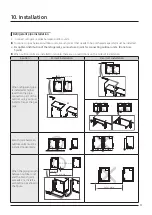
Caution for electrical work


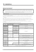
You must install ELCB or MCCB + ELB


ELCB: Earth leakage breaker


MCCB: Molded case circuit breaker


ELB: Earth leakage breaker


Do not operate the outdoor unit before completing the refrigerant pipe work.


Do not disconnect or change the cable inside the product. It may cause damage to the product.


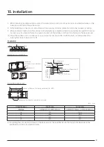
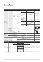
Specification of the power cable is selected based on following installation condition; culvert installation/ 

ambient temperature 30 °C/ single multi conductor cables. If the condition is different from the ones 

stated, please consult an electrical installation expert and re-select the power cable.


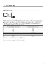
If the length of power cable exceed 50m, re-select the power cable considering the voltage drop.


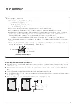
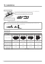
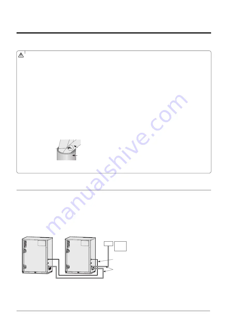
Use a power cable made out of incombustible material for the insulator (inner cover) and the sheath (outer 

cover).


Do not use the power cable with the core wire exposed due to insulator damage occurred during removal 

of the sheath. When the core wire is exposed, it may cause fire.

Insulator (inner cover)

Exposed wire core

<The example of exposed core wire>

Sheath (outer cover)

CAUTION

Power and communication cable configuration 


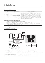
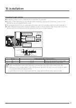
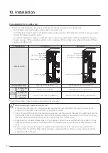
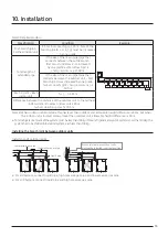
Main power and the ground cable  must be withdrawn through the knock-out hole on the bottom-right or right 

side of the cabinet.


Withdraw the communication cable from the designated knock-out hole on the bottom-right side of the front 

part. 


Install the power and communication cable using separate cable protection tube.


Fix a protection tube to the knock-out hole on the outdoor unit by using a CD connector or bushing. Make sure to 

use insulating bushing.


Make sure that power and communication cables do not block the front panel.

MCCB+ 

ELB 

ELCB

Power cable

Communication cable 

between outdoor units

or

Summary of Contents for VRF DVM S Water

Page 1: ...VRF Technical Data Book DVM S WaterforEurope R410A 50 60Hz HP HR Model Premium energy efficiency Type Premium compact type ...

Page 2: ...2 Version Modification Date Remark Ver 1 0 Release DVM S Water for Europe TDB 17 06 23 History Ver 1 01 Modify the Accessory Compatibility table for MCU kit P67 17 09 13 ...

Page 3: ...ion F 2013 H 2014 J 2015 K 2016 M 2017 4 Product Type X Outdoor Unit N Indoor Unit 5 Feature1 W DVM WATER 6 Feature2 A Standard General Temp Module 7 Rating Voltage N 3Ø 380 415V 50 60Hz G 3Ø 380 415V 50Hz 8 Mode R Heat Recovery H Heat Pump Model name RVX 100 T T F E E 100 1 2 3 4 5 6 7 8 ...

Page 4: ...plete reliability It can also reach up to a height of 50 meters 164 feet which is the equivalent of 10 stories Lowerinstallation costs great capacity The DVM S WATER air conditioning system is much more economical to install as it has a small footprint and lightweight design but a large 30 horsepower HP capacity So instead of installing two 10HP units you only need one 30HP Samsung unit using 56 l...

Page 5: ...6 2 Specification 10 3 Electric Characteristics 21 4 Dimensional Drawing 23 5 Center of Gravity 26 6 Electrical Wiring Diagram 28 7 Sound Level 30 8 Operating Range 34 9 Piping Diagram 37 10 Installation 40 11 Accessory 60 ...

Page 6: ...2 2 18 AM180MXWANR2 2 1 1 20 AM200MXWANR 1 1 22 AM220MXWANR2 2 1 1 24 AM240MXWANR2 2 2 26 AM260MXWANR2 3 2 1 28 AM280MXWANR2 2 1 1 30 AM300MXWANR2 2 1 1 32 AM320MXWANR2 2 1 1 34 AM340MXWANR2 3 1 2 36 AM360MXWANR2 3 2 1 38 AM380MXWANR2 3 1 1 1 40 AM400MXWANR2 2 2 42 AM420MXWANR2 3 1 1 1 44 AM440MXWANR2 3 2 1 48 AM480MXWANR2 3 1 2 50 AM500MXWANR2 3 1 2 52 AM520MXWANR2 3 1 2 60 AM600MXWANR2 3 3 1 Lin...

Page 7: ...e indoor unit may decrease Total capacity of the connected indoor units can be allowed from 50 to 130 of the total outdoor unit capacity 0 5 Outdoor unit capacity Total capacity of the connected indoor units 1 3 Outdoor unit capacity You can connect maximum 64 indoor units to the outdoor unit Maximum quantity of connectable indoor unit is set to 64 since outdoor unit only support up to 64 communic...

Page 8: ...7 2 2 2 8 3 6 4 5 5 6 6 0 7 1 9 0 Slim1way cassette JSF 2way cassette Global 4way cassette 4way CST 600 X 600 360 CST Floor Standing Unit Slim duct MSP duct HSP duct Ceiling Console Neo forte Neo forte with EEV Hydro unit HE Hydro unit HT ERV plus ...

Page 9: ...2 8 14 0 22 0 28 0 44 8 500CMH 1000CMH Slim1way cassette JSF 2way cassette Global 4way cassette 4way CST 600 X 600 360 CST Floor Standing Unit Slim duct MSP duct HSP duct Ceiling Console Neo forte Neo forte with EEV Hydro unit HE Hydro unit HT ERV plus ...

Page 10: ...denser Type Type PHE Plate Heat Exchanger PHE Plate Heat Exchanger PHE Plate Heat Exchanger PHE Plate Heat Exchanger Pipe Size Ø inch PT1 1 4 PT1 1 4 PT1 1 4 PT1 1 4 x 2 Pressure Drop kPa 22 0 30 0 43 0 22 0 x 2 WaterFlowRate LPM 80 0 96 0 114 0 80 0 x 2 Max Pressure Mpa 1 96 1 96 1 96 1 96 Piping Connections Liquid Pipe Type Brazed connection Brazed connection Brazed connection Brazed connection ...

Page 11: ...ate Heat Exchanger PHE Plate Heat Exchanger PHE Plate Heat Exchanger PHE Plate Heat Exchanger Pipe Size Ø inch PT1 1 4 x 2 PT1 1 4 PT1 1 4 x 2 PT1 1 4 x 2 Pressure Drop kPa 22 0 30 0 54 0 30 0 43 0 43 0 x 2 WaterFlowRate LPM 80 0 96 0 190 0 96 0 114 0 114 0 x 2 Max Pressure Mpa 1 96 1 96 1 96 1 96 Piping Connections Liquid Pipe Type Brazed connection Brazed connection Brazed connection Brazed conn...

Page 12: ...ate Heat Exchanger PHE Plate Heat Exchanger Pipe Size Ø inch PT1 1 4 x 3 PT1 1 4 x 2 PT1 1 4 x 2 PT1 1 4 x 2 Pressure Drop kPa 22 0 x 2 30 0 22 0 54 0 30 0 54 0 43 0 54 0 WaterFlowRate LPM 80 0 x 2 96 0 80 0 190 0 96 0 190 0 114 0 190 0 Max Pressure Mpa 1 96 1 96 1 96 1 96 Piping Connections Liquid Pipe Type Brazed connection Brazed connection Brazed connection Brazed connection Ø mm 19 05 19 05 1...

Page 13: ... PHE Plate Heat Exchanger PHE Plate Heat Exchanger Pipe Size Ø inch PT1 1 4 x 3 PT1 1 4 x 3 PT1 1 4 x 3 PT1 1 4 x 2 Pressure Drop kPa 30 0 43 0 x 2 22 0 x 2 54 0 22 0 30 0 54 0 54 0 x 2 WaterFlowRate LPM 96 0 114 0 x 2 80 0 x 2 190 0 80 0 96 0 190 0 190 0 x 2 Max Pressure Mpa 1 96 1 96 1 96 1 96 Piping Connections Liquid Pipe Type Brazed connection Brazed connection Brazed connection Brazed connec...

Page 14: ... Plate Heat Exchanger PHE Plate Heat Exchanger Pipe Size Ø inch PT1 1 4 x 3 PT1 1 4 x 3 PT1 1 4 x 3 Pressure Drop kPa 30 0 43 0 54 0 43 0 x 2 54 0 22 0 54 0 x 2 WaterFlowRate LPM 96 0 114 0 190 0 114 0 x 2 190 0 80 0 190 0 x 2 Max Pressure Mpa 1 96 1 96 1 96 Piping Connections Liquid Pipe Type Brazed connection Brazed connection Brazed connection Ø mm 19 05 19 05 19 05 Ø inch 3 4 3 4 3 4 Gas Pipe ...

Page 15: ...xchanger PHE Plate Heat Exchanger PHE Plate Heat Exchanger Pipe Size Ø inch PT1 1 4 x 3 PT1 1 4 x 3 PT1 1 4 x 3 Pressure Drop kPa 30 0 54 0 x 2 43 0 54 0 x 2 54 0 x 3 WaterFlowRate LPM 96 0 190 0 x 2 114 0 190 0 x 2 190 0 x 3 Max Pressure Mpa 1 96 1 96 1 96 Piping Connections Liquid Pipe Type Brazed connection Brazed connection Brazed connection Ø mm 19 05 19 05 19 05 Ø inch 3 4 3 4 3 4 Gas Pipe T...

Page 16: ...e Heat Exchanger PHE Plate Heat Exchanger PHE Plate Heat Exchanger Pipe Size Ø inch PT2 PT2 PT1 1 4 PT2 PT1 1 4 PT2 PT1 1 4 Pressure Drop kPa 50 50 22 50 30 50 43 WaterFlowRate LPM 285 285 80 285 96 285 114 Max Pressure Mpa 1 96 1 96 1 96 1 96 Piping Connections Liquid Pipe Type Brazed connection Brazed connection Brazed connection Brazed connection Ø mm 19 05 19 05 19 05 19 05 Ø inch 3 4 3 4 3 4 ...

Page 17: ...Exchanger PHE Plate Heat Exchanger PHE Plate Heat Exchanger Pipe Size Ø inch PT2 PT1 1 4 x 2 PT2 PT1 1 4 x 2 PT2 PT1 1 4 PT2 PT1 1 4 x 2 Pressure Drop kPa 50 22 x 2 50 22 30 50 54 50 43 30 WaterFlowRate LPM 285 80 x 2 285 80 96 285 190 285 114 96 Max Pressure Mpa 1 96 1 96 1 96 1 96 Piping Connections Liquid Pipe Type Brazed connection Brazed connection Brazed connection Brazed connection Ø mm 19 ...

Page 18: ...HE Plate Heat Exchanger PHE Plate Heat Exchanger Pipe Size Ø inch PT2 PT1 1 4 x 2 PT2 PT1 1 4 x 2 PT2 x 2 PT2 PT1 1 4 x 2 Pressure Drop kPa 50 43x2 50 54 22 50 x 2 50 54 43 WaterFlowRate LPM 285 114x2 285 190 80 285 x 2 285 190 114 Max Pressure Mpa 1 96 1 96 1 96 1 96 Piping Connections Liquid Pipe Type Brazed connection Brazed connection Brazed connection Brazed connection Ø mm 19 05 19 05 19 05 ...

Page 19: ...late Heat Exchanger PHE Plate Heat Exchanger PHE Plate Heat Exchanger Pipe Size Ø inch PT2x2 PT1 1 4 PT2x2 PT1 1 4 PT2x2 PT1 1 4 PT2 x 3 Pressure Drop kPa 50x2 22 50x2 30 50x2 54 50 x 3 WaterFlowRate LPM 285x2 80 285x2 96 285x2 190 285 x 3 Max Pressure Mpa 1 96 1 96 1 96 1 96 Piping Connections Liquid Pipe Type Brazed connection Brazed connection Brazed connection Brazed connection Ø mm 22 22 22 2...

Page 20: ...sults of individual installed units 4 Heating capacityes are based on Indoor temperature 20 C DB 15 C WB Inlet water temperature 10 C Outlet water temperature 7 C Equivalent refrigerant piping 7 5m Level differences 0m 5 These products contain R410A GWP 2 088 which is fluorinated greenhouse gas 6 Total capacity of the connected indoor units can be allowed from 50 to 130 of the total outdoor unit c...

Page 21: ...456 18 4 18 8 36 1 40 24 67 2 AM240MXWANR2 50 60 380 415 342 456 20 6 20 8 40 0 50 26 72 8 AM260MXWANR2 50 60 380 415 342 456 20 5 21 6 48 3 63 28 78 4 AM280MXWANR2 50 60 380 415 342 456 23 5 24 47 9 63 30 84 0 AM300MXWANR2 50 60 380 415 342 456 25 4 25 8 47 9 63 32 89 6 AM320MXWANR2 50 60 380 415 342 456 27 6 27 8 51 8 63 34 95 2 AM340MXWANR2 50 60 380 415 342 456 28 7 29 2 56 1 63 36 100 8 AM360...

Page 22: ...2 456 43 7 43 9 79 8 90 52 145 6 AM520MXWANR1 50 60 380 415 342 456 44 8 45 3 84 1 100 54 151 2 AM540MXWANR1 50 60 380 415 342 456 47 47 3 88 0 100 58 162 4 AM580MXWANR1 50 60 380 415 342 456 49 9 50 5 95 9 125 60 168 0 AM600MXWANR1 50 60 380 415 342 456 52 8 53 96 0 125 62 173 6 AM620MXWANR1 50 60 380 415 342 456 54 54 3 99 8 125 68 190 4 AM680MXWANR1 50 60 380 415 342 456 59 59 6 112 1 125 70 19...

Page 23: ...1 6 7 8 Unit mm No Name Description No Name Description 8HP 10HP 12HP 8HP 10HP 12HP Liquid ref pipe 9 52 3 8 9 52 3 8 12 70 1 2 Water inlet pipe PT1 1 4 High pressure gas ref pipe 15 88 5 8 19 05 3 4 19 05 3 4 Communication wiring Low pressure gas ref pipe 19 05 3 4 22 22 7 8 28 58 11 8 External contact wiring Water outlet pipe PT1 1 4 Powerwiring ...

Page 24: ... 418 308 203 142 180 138 78 4 5 3 2 1 6 7 8 Unit mm No Name Description No Name Description Liquid ref pipe 15 88 5 8 Water inlet pipe PT1 1 4 High pressure gas ref pipe 28 58 1 1 8 Communication wiring Low pressure gas ref pipe 28 58 1 1 8 External contact wiring Water outlet pipe PT1 1 4 Powerwiring ...

Page 25: ...42 545 138 78 92 1104 995 542 88 66 43 Unit mm No Name Description No Name Description Liquid ref pipe Ø 19 05 3 4 Water inlet pipe PT2 Gas ref pipe Ø 28 58 1 1 8 Communication wiring High pressure gas ref pipe Ø 34 92 1 3 8 External contact wiring Water outlet pipe PT2 Powerwiring ...

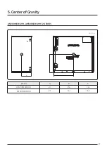
Page 26: ...26 AM080 100 120MXWA 8 10 12HP A B C Unit mm Model A B C AM080 100 120MXWA 211 345 353 5 Centerof Gravity ...

Page 27: ...27 AM200MXWA AM300KXWA 20 30HP A B C Unit mm Model A B C AM200MXWA 210 476 362 AM300KXWA 206 461 390 5 Centerof Gravity ...

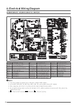
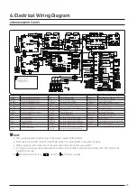
Page 28: ...ter COMP2 COMM PCB Printed circuit board Communication CONDENSER OUT 10K Temp Sensor CondenserOutTemp _10Kohm MAIN COOLING SolenoidValve Main Cooling COMP1 Motor Compressor1 COMPTOP1 200K Temp Sensor Compressor1_200Kohm F101 250V T2A FUSE INVERTER PBA COMP2 Motor Compressor2 COMPTOP2 200K Temp Sensor Compressor2_200Kohm 690V T40A FUSE NOISE FILTER EVIV V1 SolenoidValve EVI1 DISCHARGE1 200K Temp Se...

Page 29: ...sor1 OIL COMP2 Oil Sensor Compressor2 HOTGAS2V V SolenoidValve Hot Gas Bypass2 COMP2 Motor Compressor2 OUT 10K Temp Sensor Ambient Temp _10Kohm OD EEVV V SolenoidValve OutdoorEEV FAN1 Motor OutdoorFan1 COND 10K Temp Sensor Cond Out Temp _10Kohm 690V T56A FUSE NOISE FILTER FAN2 Motor OutdoorFan1 TOP1 200K Temp Sensor CompressorTop1_200Kohm MODE CHANGE Connector Remote switching cool heat selector E...

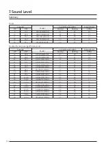
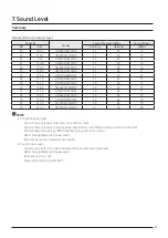
Page 30: ... AM160MXWANR2 49 50 64 18 50 4 AM180MXWANR2 50 51 65 22 61 6 AM220MXWANR2 51 53 69 24 67 2 AM240MXWANR2 51 54 71 26 72 8 AM260MXWANR2 51 53 66 28 78 4 AM280MXWANR2 52 53 71 30 84 0 AM300MXWANR2 52 54 71 32 89 6 AM320MXWANR2 52 55 72 34 95 2 AM340MXWANR2 52 55 71 36 100 8 AM360MXWANR2 53 54 71 38 106 4 AM380MXWANR2 53 55 71 40 112 0 AM400MXWANR2 54 56 74 42 117 6 AM420MXWANR2 54 56 73 44 123 2 AM44...

Page 31: ...9 62 173 6 AM620MXWANR1 58 60 77 68 190 4 AM680MXWANR1 60 62 79 70 196 0 AM700MXWANR1 60 62 79 80 224 0 AM800MXWANR1 60 62 79 90 252 0 AM900MXWANR1 61 63 80 NOTE Sound Pressure Level Sound Pressure level is obtained in an anechoic room Sound Pressure level is a relative value depending on the distance and acoustic environment Sound Pressure level may differ depending on operation condition dBA A w...

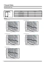
Page 32: ...NR 65 NR 60 NR 55 NR 50 NR 45 NR 40 NR 35 NR 30 NR 25 NR 20 NR 15 Hearing threshold Cooling NR 90 NR 85 NR 80 NR 75 NR 70 0 5 10 15 20 25 30 35 40 45 50 55 60 65 70 75 80 85 90 0 5 10 15 20 25 30 35 40 45 50 55 60 65 70 75 80 85 90 63 125 250 500 1000 2000 4000 8000 Sound Pressure Level dB Octave Band Center Frequency Hz 4 AM200MXWA NR 65 NR 60 NR 55 NR 50 NR 45 NR 40 NR 35 NR 30 NR 25 NR 20 NR 15...

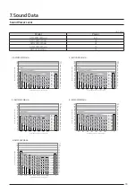
Page 33: ...uency Hz 3 AM120MXWA NR 70 NR 65 NR 60 NR 55 NR 50 NR 45 NR 40 NR 35 NR 30 NR 25 NR 20 NR 15 0 5 10 15 20 25 30 35 40 45 50 55 60 65 70 75 80 85 90 0 5 10 15 20 25 30 35 40 45 50 55 60 65 70 75 80 85 90 95 100 105 110 95 100 105 110 125 250 500 1000 2000 4000 8000 A Sound Power Level dB Octave Band Center Frequency Hz 4 AM200MXWA NR 70 NR 65 NR 60 NR 55 NR 50 NR 45 NR 40 NR 35 NR 30 NR 25 NR 20 NR...

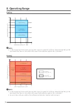
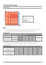
Page 34: ...utlet water temperature C Indoor temperature C DB 10 5 0 15 10 20 25 30 10 20 30 35 40 50 45 Warmingup operation range Anti freeze A Anti freeze B Operation Range Operation Range Continuous Operation Range Antifreeze A freezing point 8 Antireeze B freezing point 15 NOTE In the range except for the continuous operation range the protection control can be active depending on the heat source flow rat...

Page 35: ...Circulating water Operation Intel water temperature C Standard Main usage Operation limit Heat source water Water loop Cooling 30 20 35 10 45 Heating 20 20 35 Ground heat source 1 Ground water Cooling 15 15 35 Cooling 10 45 Heating 5 45 Heating 5 45 2 Heating 10 5 25 Ground loop Cooling 25 15 35 Heating 5 5 25 1 Anti freeze must be used when temperature of water inlet for heating is below10 C or g...

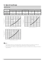
Page 36: ... 150 250 Water Flow rate of cooling water L min Pressure Drop from plate type heat exchanger kPa AM200MXWA Water Flow rate of cooling water L min Pressure Drop from plate type heat exchanger kPa 80 70 60 50 40 30 20 10 0 0 200 100 300 400 80 70 60 50 40 30 20 10 0 AM300KXWA NOTE When the water flow rate is out of the operation range stop the outdoor unit and take care of the cause before restartin...

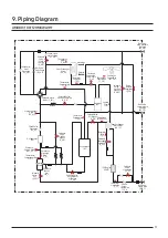
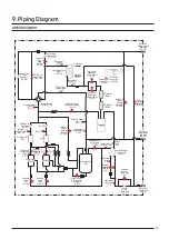
Page 37: ..._HG2 Valve Pressure Regulating V_PR Thermistor CondOut T_CO Thermistor ControlBox T_CB Thermistor Water T_W SolenoidValve HotGasCharging V_HC Check Valve Liquidpipe CV_L IPMCooler IPMC Electronic Expansion Valve Main E_M Thermistor CompressorTop T_CT Thermistor Discharge Pipe T_D OilSeparator OS Solenoid Valve HotGas bypass V_HG CheckValve Discharge CV_D Pressure Sensor Low PS_L SolenoidValve Accu...

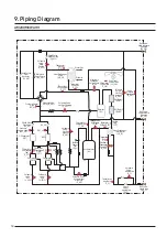
Page 38: ..._PR Thermistor CondOut T_CO Thermistor Water T_W SolenoidValve HotGasCharging V_HC Check Valve Liquidpipe CV_L IPMCooler1 IPMC1 IPMCooler2 IPMC2 Electronic Expansion Valve Main E_M Thermistor Compressor Top1 T_CT1 Thermistor Discharge Pipe1 T_D1 OilSeparator1 OS1 OS2 Solenoid Valve HotGas bypass1 V_HG1 CheckValve Discharge1 CV_D1 CV_D2 Solenoid Valve EVI2 V EVI2 SolenoidValve Accumulator oilReturn...

Page 39: ... V_PR Thermistor CondOut T_CO Thermistor Water T_W SolenoidValve HotGasCharging V_HC Check Valve Liquidpipe CV_L IPMCooler1 IPMC1 IPMCooler2 IPMC2 Thermistor Compressor Top1 T_CT1 Thermistor Discharge Pipe1 T_D1 OilSeparator1 OS1 OS2 CheckValve Discharge1 CV_D1 CV_D2 Solenoid Valve EVI2 V EVI2 SolenoidValve Accumulator oilReturn V_AR Solenoid Valve EVI V_EVI1 Pressure Switch High1 PW_H1 Accumulato...

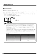
Page 40: ...n the left page at the interface point power service box of the user s supply The user must ensure that this device is connected only to a power supply system which fulfills the requirement above If necessary the user can ask the public power supply company for the system impedance at the interface point This equipment complies with IEC 61000 3 12 provided that the short circuit power Ssc is great...

Page 41: ...material for the insulator inner cover and the sheath outer cover Do not use the power cable with the core wire exposed due to insulator damage occurred during removal of the sheath When the core wire is exposed it may cause fire Insulator inner cover Exposed wire core The example of exposed core wire Sheath outer cover CAUTION Powerand communication cable configuration Main power and the ground c...

Page 42: ...ion the cable with a protection tape or bushing etc CAUTION Powerwiring diagram Supplying 3 phase 4 wires 380 415 V 3 phase 4 wires 380 415 V Main outdoor unit Main outdoor unit Sub outdoor unit Sub outdoor unit Communicationcable Outdoor unit Outdoorunit Main outdoor unit Sub outdoor unit 1 Sub outdoor unit 2 Communicationcable Outdoorunit Indoorunit Grounding Grounding Grounding Wired remote con...

Page 43: ...ould get damaged MCCB ELB or ELCB 3 phase 380 415 V External power supply External contact signal Communication cable Indoor Outdoor unit Protection tube for power cable Conduit field supply Conduit mounting plate Lock nut field supply Sub unit 3 phase 380 415 V Knock out hole Screw Tightening torque for terminal N m M4 1 2 1 8 Single phase 220 240 V power cable M8 5 5 7 3 3 phase 380 415 V power ...

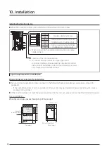
Page 44: ...ion manual of corresponding interface module Space requirement forinstallation Minimum space requirement forinstallation Secure minimum installation space as shown in the following figures considering service area and path for people etc If the installation space is narrow installer or otherworker may get injured during work and may also cause problem to the product If the conditions does not meet...

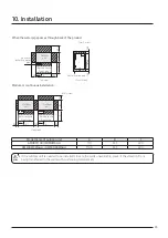
Page 45: ... Module or continuous installation Top view Unit mm Service space Front side C 20 Outdoor unit 350 A 100 B 300 350 A 100 Service space Front side Outdoor unit Model name of outdoor unit A B C AM080 100 120MXWA 770 545 600 AM200MXWA AM300KXWA 1100 545 600 If the outdoor unit is needed to be installed close to the walls unavoidably prevent the vibration from being transferred to the walls with cushi...

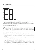
Page 46: ...nufacturer is not responsible for the damage occurred by not following the installation standards 1 Make sure that the height of the base ground is 150 mm or higher to protect the outdoor unit from rain water or other external conditions Also install a draining pit around the base ground and connect the drain pipe to the drainage 2 Considering the vibration and weight of the outdoor unit strength ...

Page 47: ... fix it with the bolt nut and washer The bearing force has to be over 3 5 kN Foundation Ditch 150mm or more Outdoor unit installation Base ground Foundation or H beam or anti vibration frame Outdoor unit Anchor bolt Nut Spring washer Foundation or H beam or anti vibration frame Anti vibration pad Over A 10 20 mm A 20 mm Anchor Bolt Insertion depth 50mm or more Fixing the outdoor unit A B 54 C D 54...

Page 48: ... and accessories compatible with R 410A refrigerant gas Tool Installation process purpose Compatibility with conventional tool Pipe cutter Refrigerant pipe installation Pipe cutting Compatible Flaring tool Pipe flaring Refrigerant machine oil Apply refrigerant oil on flared part Exclusive ether oil ester oil alkali benzene oil or synthetic oil Torque wrench Connect flare nut with pipe Compatible P...

Page 49: ...utdoor unit and the farthest indoor unit exceeds 90 m you must increase the size of the liquid pipe by one grade among the pipes main pipe which connects between the outdoor unit to the first branch joint Main pipe size Outer diameter mm If total pipe length is less than 90 m Main pipe size Outer diameter mm If total pipe length is 90 m or longer 9 52 12 70 12 70 15 88 15 88 19 05 19 05 22 22 22 2...

Page 50: ...llation B Type PBA Key mode K1 K2 Set as ht 00 Factory default Set as ht 01 Set during installation Referto the outdoorunit keyfunction option switch and keyfunction Caution forwelding the pipe to an outdoorunit When welding the pipe the unit may get damaged by the heat and flame from welding Use a flame proofing cloth to protect the unit from a brazing fire or flame The O ring and Teflon packing ...

Page 51: ...or units are installed in module there are no restrictions on the order of installation Caution Correct installation Incorrect installation When refrigerant pipe is installed at higher level than the pipe connection part of the outdoor unit you must install a trap at the gas pipe 200 mm or more Branch joint between outdoor units must be installed horizontally When the piping length between outdoor...

Page 52: ...a b c d e f g h i 500 m Outdoor unit Outdoor unit Module installation Pipe length 10 m or less r 10 m s 10 m t 10 m Equivalent length 13 m or less r 13 m s 13 m t 13 m High difference 1 5 m or less H5 1 5 m H5 Maximum allowable height difference Outdoor unit Indoor unit 50 40 m Note 2 H1 50 40 m Indoor unit Indoor unit 50 m or less H2 50 m Maximum allowable length after branch joint First branch j...

Page 53: ...oor unit to the farthest indoor unit and nearest indoor unit 45 m a b c d e f g p a h 45 m Note 2 When indoor unit is located at higher level than outdoor unit allowable height difference is 40m but when the indoor unit is located at lower level than outdoor unit allowable height difference is 50 m Total refrigerant amount of the system must be less than100kg If total refrigerant amount of system ...

Page 54: ...n part of the outdoor unit connection pipe or the provided socket according to the diameter of the connection pipe before connecting them Over10 15 mm NOTE Installing the MCU MCU specification Model MCU S6NEK2N MCU S4NEK3N MCU S2NEK2N MCU S1NEK1N Exterior of MCU Number of connectable indoor units at one port Up to 8 units Up to 8 units Up to 8 units Up to 8 units The maximum capacity of the connec...

Page 55: ...combination at below Connectable port combination for Y connector A B port C D port E F port Non connectable port combination for Y connector B C port D E port non continuous port Set Dip Switch option for using Y connector 1 ON 2 3 4 1 ON 2 3 4 1 ON 2 3 4 1 ON 2 3 4 S W Option S W Option S W Option S W Option Default Combination of A B port Combination of C D port Combination of E F port In case ...

Page 56: ...nection welding High pressure gas pipe connection welding Liquid pipe connection welding When installing MCU use the pattern sheet for installation that is provided with the product When welding the gas pipes protect the product with the flame proof sheet When connecting the MCU with outdoor units default direction is set in the MCU If installing opposite direction weld the enclosed copper cap in ...

Page 57: ...r pipe circuit freezes it will cause damage to the plate type heat exchanger and therefore preventive measure must be taken according to the situation Drain remaining water in the water pipe when it will not be used for long period of time Constantly operate the water pump to circulate the waterwithin the water pipe Install self regulating heat cable on the water pipes CAUTION Design condition Typ...

Page 58: ... the necessary work is not done thoroughly you will waste energy caused by thermal loss and may get property damage during cold seasons when water pipe freezes and bursts 7 If you stop the product for long time or in night time water pipe circuit may freeze naturally when the temperature around the outdoor unit is under 0 C When water pipe circuit freezes it will cause damage to the plate type hea...

Page 59: ...se circulating pump to remove foreign substance within the water pipes and clean the strainer When foreign substances accumulates on outdoor unit plate type heat exchanger it may break the heat exchanger or cause problem to it 13 For legal facilities install digital sensor and flow meter on the water pipe for monitoring Open the valve of the water pipe connected to the outdoor unit after flushing ...

Page 60: ...Wired Remote Controller Simple Type MWR SH00N DVM CAC Wired Remote Controller Touch Simple Type MWR SH10N DVM CAC ERV Wired Remote Controller MWR VH12N ERV Olny DVM CAC Wired Remote Controller MWR WW00N EHS Only EHS Receiver KIT MRK A10N DVM CAC Zone Controller MWR ZS00N Master controller Damper controller DVM CAC Zone Controller MWR ZS10N Slave controller DVM CAC Zone Controller MRW TS External r...

Page 61: ...M N01 DVM CAC ERV Interface Module MIM N10 DVM CAC Integrated management System DMS2 5 MIM D01AN DVM CAC S NET3 MST P3P DVM CAC Gate Way BACnet Gateway MIM B17BN DVM CAC Lonworks Gateway MIM B18BN DVM CAC External Contact Interface Module MIM B14 DVM CAC MTFC Multi Tenant Function Controller MCM C210N DVM SIM Signal Interface Module MIM B12N DVM CAC PIM Pulse Interface Module MIM B16N DVM CAC 11 A...

Page 62: ...AC Others External Room Sensor MRW TA DVM CAC Operation Mode Selection Switch MCM C200 DVM Module Controller MCM A00N CHILLER Only CHILLER FCU Interface Module MIM F10N CHILLER Only CHILLER NOTE In case you want more information about the accessories please refer to the control and accessories TDB on pvi Samsung com site ...

Page 63: ...H03N MIM H03 DVM CAC Interface Module MIM N01 MIM N01 DVM CAC ERV Interface Module MIM N10 MIM N10 DVM CAC Integrated management System DMS2 5 MIM D01AN MIM D00A DVM CAC S NET3 MST P3P MST P3P DVM CAC Gate Way BACnet Gateway MIM B17BN MIM B17 DVM CAC Lonworks Gateway MIM B18BN MIM B18 DVM CAC External Contact Interface Module MIM B14 MIM B14 DVM CAC MTFC Multi Tenant Function Controller MCM C210N ...

Page 64: ...r Y Joint Only H R Outdoor Unit MXJ TA3100M 135 2 kW and below MXJ TA3800M 140 2 kW and Over Distribution Header MXJ HA2512M 45 0 kW and below for 4 rooms MXJ HA3115M 70 3 kW and below for 8 rooms MXJ HA3819M Over70 3kW 135 2kWandbelow for8rooms MCU MCU S6NEK2N 6 ports max 61 6kW 16kW 1port MCU S4NEK3N 4 ports max 61 6kW 16kW 1port MCU S2NEK2N 2 ports max 32 0kW 16kW 1port MCU S1NEK1N 1 port max 1...

Page 65: ...SMEN 4Way Cassette S 600x600 Classic PC4NUSKAN 4way Cassette S Waffle PC4NUSKEN 4way Cassette S Classic PC4NBSKAN 4way Cassette S Waffle Black PC4NUDMAN 360 CST Square White PC4NUNMAN 360 CST Circular White PC4NBDMAN 360 CST Square Black PC4NBNMAN 360 CST Circular Black S Plasma lon KIT MSD CAN1 Option 1Way 4Way 4Way 600x600 360 Big Ceiling Include Console MSD EAN1 Option Duct S Big Duct ERV ERV P...

Page 66: ...ct 2 0 14 0 kW MDP G075SP Duct S External All Capacities BIG Duct MDP G075SQ Duct S Internal 3 5 kW 14 kW BIG Duct AHU KIT MXD K025AN 7 0 kW 8 75 kW MXD K050AN 14 0 kW 17 5 kW MXD K075AN 21 0 kW 26 25 kW MXD K100AN 28 0 kW 35 0 kW MXD A64K100E MCM D201N 28kW 35kW 56kW 70kW 84kW 105kW 112kW 140kW MDX A64K100E X 1 EA MDX A64K100E X 2 EA MDX A64K100E X 3 EA MDX A64K100E X 4 EA Transformer kit MVR TK0...

Page 67: ...MDP E075SEE3D O MDP G075SP External AllCapacities O O MDP G075SQ Internal O O S Plasma Ion KIT MSD CAN1 O O MSD EAN1 O Motion detect Sensor MCR SMA O ERV CO2 Sensor MOS C1 O EEV KITS MEV E SA 1 Indoor O MXD E K A 2 3 Indoor O MCU KIT MCU S6NEK2N 6 ports max61 6kW O O O O O O O O O O O O O O O O O O O O O O MCU S4NEK3N 4 ports max61 6kW O O O O O O O O O O O O O O O O O O O O O O MCU S2NEK2N 2 port...

Page 68: ... PM SE Head Office Suwon Korea 129 Samsung Ro Yeongtong Gu Suwon City Gyeonggi Do Korea 16677 Website www samsung com http btsp samsunggsbn com Email airconditioner samsung com Images and data in this book may subject to change without prior notice ...

Reviews: