21
Samsung Electronics
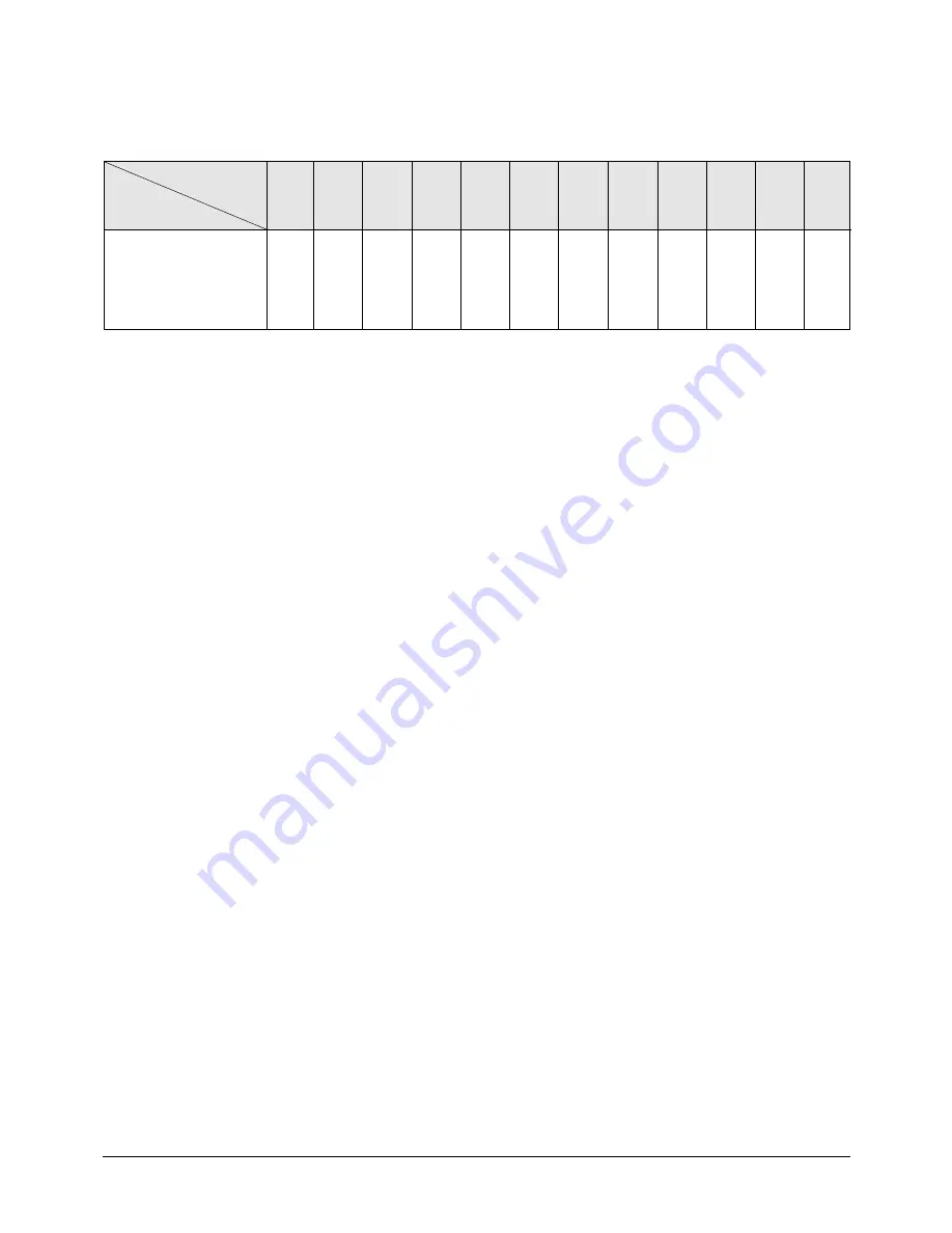
Set Up the Model Option
■
OPTION ITEMS
MODEL
REMOTE
CONTROL SEG1
SEG2
SEG3
SEG4
SEG5
SEG6
SEG7
SEG8
SEG9
SEG10 SEG11 SEG12
CH094EAM
0
4
5
1
E
DB98_22253A(1)_1 05/2/21 11:24 PM Page 21
Page 1: ...RVICE Manual CONTENTS AIR CONDITIONER 1 Product Specifications 2 Disassembly and Reassembly 3 Refrigerating Cycle Diagram 4 Set Up the Model Option 5 Control Specification 5 Troubleshooting 6 Exploded Views and Parts List 7 Block Diagram 8 Wiring Diagram 9 Schematic Diagram ...
Page 2: ... mm D mm Weight Net Gross kg Fan Speed Hi r p m Low r p m m3 min Noise Level Cooling Hi dB A Sound Pressure Heating Hi dB A Fan Type Motor Output W Type Compressor Model Motor Output kW Protection MODEL INDOOR UNIT OUTDOOR UNIT 32 000 9 400 34 800 10 200 1 220 240 50 3 350 3 270 15 3 15 0 600 550 500 450 26 24 22 20 45 45 Slit 2 x 8 x 1 4mm Turbo 39 230 840 840 27 32 930 360 67 63 64 Propeller 122...
Page 3: ... Gross kg Pipe O D Size Liquid mm inch Gas mm inch Connection Method Between Height m Pipe Length m MODEL INDOOR UNIT OUTDOOR UNIT R410A 1 750 60 Elec Expansion Valve Louver 2 x 36 x 1 5 798 880 310 74 82 9 52 3 8 15 88 5 8 Flare Max 15 Max 30 Outdoor Unit Piping CH094EAM UH094EAMC Row x Stages x Fin pitch Type Type Control ...
Page 4: ... 2 1 Indoor Unit Unit mm 1 2 Dimensions No 1 2 3 4 5 6 Name Liquid pipe connection Gas pipe connection Drain pipe connection Power supply connection Air discharge grille Air suction grille ø9 52 3 8 ø15 88 5 8 CH094EAM Model ...
Page 5: ...Samsung Electronics 4 Product Specifications 1 2 2 Outdoor Unit Unit mm 880 310 798 ...
Page 6: ...15 10 5 0 5 10 15 20 25 30 15 0 17 0 19 0 21 0 23 0 25 0 31 0 29 0 27 0 33 0 35 0 37 0 High Pressure kgf cm 2 G Heating Mode 5 5 15 20 25 30 35 40 45 6 0 6 5 7 0 7 5 8 0 8 5 9 0 9 5 10 0 Low Pressure kgf cm 2 G Cooling Mode CH094EAM UH094EAMC ...
Page 7: ...ssembly of Front Grille 1 Open the Front Grille at about 45 degrees and draw it forward 2 Disassemble the Safety Clip 3 Filter Disassembly 1 Draw the Dust Collecting Filter forward 2 Disassemble the Filter 2 Disassembly and Reassembly 2 1 Indoor Unit Stop operation of the air conditioner and remove the power cord before repairing the unit ...
Page 8: ...e 4 bolts slowly 5 Loosen the bolt of the front net to disassemble the safety net 6 Loosen the 4 bolts in the mark to uncover the Component Electric Box cover 7 Disassemble the 3 cables between the indoor unit and the Panel Stepping Motor Connector Receiving Display Unit Connector Option ...
Page 9: ... indoor unit and disassemble the Front Panel 9 Take away the disassembled Panel out of the main body 1 Disconnect all the Indoor and Outdoor Cables Connected to the Terminal Board 1 Disassemble the Fan Motor wire connector thermistor wire connector and Drain Pump wire connector 2 Disassemble the wire connector in the Capacitor Disassembly and Reassembly ...
Page 10: ...ts Procedure Remark 3 Disassemble the ground wire 4 Disassemble the Float Switch wire connected to the Terminal Port F1 F2 5 Loosen the 8 bolts in the mark 6 Loosen a bolt in the arrow direction and inside 7 Disassemble the Drain Cushion from the main body ...
Page 11: ...ake out the washer Take out the washer Take out the washer Take out the washer Take out the washer Take out the washer Take out the washer Take out the washer Take out the washer Take out the washer Take out the washer Take out the washer Take out the washer Take out the washer Take out the washer Take out the washer Take out the washer Take out the washer Take out the washer Take out the washer T...
Page 12: ...ssembly and Reassembly No Parts Procedure Remark 4 Pump 12 Loosen 3 nuts to disassemble the Motor 1 Loosen the 4 bolts of the Drain Pump 2 Disassemble the Hose from the Drain Pump 3 Disassemble the Pump from the main body Bracket ...
Page 13: ...at Exchanger 1 Disassemble the cover pipe beside the main body 2 Loosen the 2 bolts fixing the Heat Exchanger to the indoor unit Base 3 Disassemble the 4 fixing Brackets of the Heat Exchanger to disassemble it from the main body Disassembly and Reassembly ...
Page 14: ... Procedure Remark 6 Front Panel PCB Panel 1 Loosen 2 bolts fixing the Control Panel and then lift it up 2 Disassemble the Clamp 3 Loosen the bolt fixing the PCB to disassemble the PCB 4 Disassemble the PCB Wire from the PCB 5 Disassemble the Bottom PCB and PCB ...
Page 15: ...ront Panel Stepping Motor 1 Loosen 2 bolts fixing the Control Panel and then lift it up 2 Disassemble the Stepping Motor and disassemble the link 3 Disassemble the Motor from the Bracket and disassemble the Motor Wire Connected Disassembly and Reassembly ...
Page 16: ...the Cover Control 2 Detach the connection wire from the Terminal Block 3 Loosen the fixing screws and detach the Upper Cabinet 4 Loosen the fixing screws and detach the Front Cabinet 5 Loosen 2 screws and pull up the Control Box 6 Detach the terminal cover and detach the Comp lead wire 2 2 Outdoor Unit ...
Page 17: ...e Remark 2 Fan Motor 7 Loosen the fixing screws and detach the Cabinet Side 1 Loosen the fixing bolt and detach the Fan 2 Loosen 4 fixing bolts to detach the Motor 3 Loosen 4 fixing bolts to detach the Bracket Motor Disassembly and Reassembly ...
Page 18: ...edure Remark 3 Heat Exchanger Compressor 1 Release the refrigerant at first 2 Disassemble the inlet and outlet pipe by welding 3 Loosen the fixing screws of the Heat Exchanger 4 Detach the Heat Exchanger 5 Loosen four bolts of the Compressor 6 Detach the Compressor ...
Page 19: ...ng per extension length of 1m When extending the pipe length by more than 7 5m 60gr of R410A refrigerant should be refilled per extension length of 1m Heat Exchanger Evaporator Heat Exchanger Condensor Cooling Heating Gas leak check point Capillary tube Liquid pipe Gas pipe Compressor Muffle Accumulator 3 Way valve Expansion valve Filter Filter 3 Way valve ...
Page 20: ...sh the button the display panel reads or repeatedly Push the button to set the display panel to Every time you push the button the display panel reads repeatedly Setting is not required if you must a value which has a default 3 Push the button to set the display panel to Every time you push the button the display panel reads repeatedly 4 Push the button to set the display panel to Every time you p...
Page 21: ...ction key to set the display part to and check the display part The display part shows Press the Mode Selection key to set the display part to and check the display part The display part shows Step 4 Pressing the ON OFF button When pressing the operation ON OFF key with the direction of remote control for unit the sound Ding or Diriring is heard and the OPERATION ICON lamp of the display is flicke...
Page 22: ...21 Samsung Electronics Set Up the Model Option OPTION ITEMS MODEL REMOTE CONTROL SEG1 SEG2 SEG3 SEG4 SEG5 SEG6 SEG7 SEG8 SEG9 SEG10 SEG11 SEG12 CH094EAM 0 4 5 0 0 0 1 E 0 0 0 0 ...
Page 23: ... side is If SW02 MAIN that set indoor unit address is controlled to indoor unit number marked on outdoor unit is marked by 5 1 2 Option set part for Outdoor unit PCB 5 Control Specification Troubleshooting 5 1 Operation Specification DISPLAY PART DS1 Left Right Counts of Indoor Unit Installation 1 2 3 4 5 6 7 8 9 10 11 12 13 14 15 1 2 3 4 5 6 7 8 9 A B C D E F Numbers of the switch Example When th...
Page 24: ... 3 4 Use the K1 only for heat pump models K1 Displayed on SEG 3 4 Adding refrigerant at heating mode Test operation at heating mode End K2 Displayed on SEG 3 4 Adding refrigerant at cooling mode Test operation at cooling mode Pump Down for recovery of refrigerant End K3 Displayed on SEG 3 4 Reset K4 Displayed on SEG 3 4 Displays data Summary of KEY functions K1 K2 K3 RESET DISPLAY MODE CHECK MODE ...
Page 25: ...dels Pump Down for recovery of refrigerant End Reset Discharge temperature of compressor Temperature of outdoor heat exchanger Outdoor temperature Step of electronic expansion valve 0 step all closed 480 step all open Temperature of evaporator Indoor temperature Stopping view mode display communication data 110 C 38 C 34 C 120STEP 12 x 10 2 C 12 C 22 C KEY Number of press Item Example Display Mean...
Page 26: ...re sensor Error of the discharge temperature sensor 1 No communication for 2 minutes between indoor units Communication error for more than 2 minutes 2 Indoor unit receiving the communication error from outdoor unit 3 Outdoor unit tracking 3 minutes error 4 When sending the communication error from the outdoor unit the mismatching of the communication numbers and installed numbers after completion...
Page 27: ... by communication error after completion of tracking Mismatching of the indoor unit numbers set with those communicated after completion of tracking Error of float switch in indoor unit Error of setting option switches for optional accessories OPEN SHORT error of room sensor in indoor unit OPEN SHORT error of eva in sensor in indoor unit EEPROM option error Error of fan starting Open error of elec...
Page 28: ...rotection control Reverse phase error Protection control In removing frost Error of the outdoor temperature sensor Open Short Error of condenser temperature sensor Open Short Error of discharge temperature sensor Open Short System down caused by communication error after completion of tracking Mismatching of the indoor unit numbers set with those communication after completion of 5 times tracking ...
Page 29: ...onnection or leak of applied sensor Yes No Yes Check the out temp sensor is normal or not by use of out data display part Check the temp data is normal or not after pressing K4 3 times At this time is occurred the difference between the out temp and data Reoperation after PCB replacement Does the out temperature sensor connected to PCB CN41 At this time Is largely deviate the resistance value from...
Page 30: ...normal or not after pressing K4 2 times At this time is occurred the difference between the out temp and data Reoperation after PCB replacement Does the out heat exchanger temp sensor connected to PCB CN41 At this time Is largely deviate the resistance value from side table value Measure the resistance value between two terminals after separating the out heat exchanger temp sensor connector from P...
Page 31: ...Does the outdoor discharge temp sensor connected to PCB CN42 At this time Is largely deviate the resistance value from side table value Measure the resistance value between two terminals after separating the outdoor discharge temp sensor connector from PCB Temp C 130 120 100 80 60 25 20 10 0 Resistance kΩ 8 9 11 2 18 5 32 59 200 242 362 553 Outdoor unit display Indoor unit display How to determine...
Page 32: ...by each and then replace the indoor unit PCB after line check Check the display after pressing the reset key on outdoor PCB When tracking is there any indoor answer from display part At this time is the voltage between lines rectangular wave over DC 0 7V like below figure 0 7V 0 7V Good Bad Multi type After 2 minutes check if PCB address setting of indoor unit displayed the communication error amo...
Page 33: ...s To measure the 2 lines of outdoor unit side by use of scope after removing the communication line connecting from outdoor unit to indoor unit Is equal indoor unit actual installation number and installation number setting switch At this time is the voltage between lines rectangular wave over DC 0 7V When tracking is there any indoor answer from display part If address is not fault exchange the i...
Page 34: ... connected to indoor unit PCB Open status Is much the water of drain pan Does the drain pump operate Does the water level decrease Is the same error occurred Is the terminal voltage of drain pump PCB about AC220V Re assembly the floating switch connector and perform the reset of outdoor power Required the reset of indoor unit power Note E3 error should be released when indoor unit power is reset O...
Page 35: ... 17 18 21 10 11 13 12 15 20 24 22 23 2 1 5 6 8 7 3 4 9 25 26 27 19 31 30 28 29 32 6 Exploded Views and Parts List 6 1 Indoor Unit You can search for the updated part code number through the ITSELF URL http itself sec samsung co kr ...
Page 36: ...WAY CASSETTE 1 SA 14 DB64 00721A CABINET SIDE AFPCH072EA0 SGCC M T0 7 DPM 7200W 4 WAY 1 SA 15 DB90 01082A ASS Y CABINET BACK CH070EZM NEW 4WAY CASSETTE 1 SA 16 DB90 01092A ASS Y COVER PIPE CH140EZM CH070EZM 1 SA 17 DB90 01010A ASS Y COVER DRAIN CH140EZM NEW 4WAY CASSETTE 1 SA 18 DB94 00345B ASS Y HOSE DRAIN NO NO 132 7 NO R22 CH140EZM 1 SA 19 DB90 01261A ASS Y HOLDER EVAP CH105EZM 1 SA 20 DB96 044...
Page 37: ...Samsung Electronics 36 6 2 Panel 28 28 16 15 30 28 1 18 13 12 14 31 11 7 17 28 32 28 23 21 22 10 28 18 30 29 29 4 5 6 8 29 3 26 9 27 19 20 25 28 2 24 ...
Page 38: ...SHER 1 SNA 14 DB69 00947A CUSHION IN EPS 4 SA 15 DB69 00948A CUSHION OUT EPS 4 SNA 16 DB63 01014A COVER A HIPS 1 SA 17 DB63 01015A COVER B HIPS 1 SA 18 DB63 01016A COVER C HIPS 2 SA 19 DB64 01144A GRILLE AIR INLET HIPS 1 SA 20 DB74 00002A FILTER AIR COMPOUNDED PP 1 SA 21 DB64 01145A KNOB SLIDE HIPS 2 SA 22 DB67 00030A SPRING KNOB STS304 2 SA 23 DB63 01036A COVER KNOB HIPS 2 SA 24 DB70 00302A PLATE...
Page 39: ...Samsung Electronics 38 6 3 Outdoor Unit 16 2 2 2 1 2 4 18 20 26 2 8 14 15 19 1 6 25 24 22 23 3 21 12 11 13 10 5 7 17 10 2 10 10 1 10 3 10 8 10 7 10 6 10 4 18 1 5 9 4 17 1 2 3 ...
Page 40: ...A CASE PCB UH070EZM ABS 2 5 BLACK DPM 5V 1 SA 10 6 2301 001367 C FILM LEAD OTHER 6000nF 10 5 450V BK 58x25x40mm 1 SA 10 7 2501 001236 C OIL 30uF 450V BK 53x85mm 20 6 2 SA 10 8 DB61 02319A CLIP CAPACITOR UH094EAMC SSEC 1 SA 11 DB32 00102A THERMISTOR OUT 204CT 200K 25 3435K 20 150 50mA 5V SSEC 1 SA 12 DB32 00101A THERMISTOR OUT 204CT 200K 25 3435K 20 150 50mA 5V SSEC 1 SA 13 DB93 02919C ASS Y PCB MA...
Page 41: ...on EEPROM option saving and blackout restoring function Power comm line misconnection prevention function Cost saving related sub option separation between indoor unit communication part Option part sub development according to the SVC structure Blackout restoring function RMC ADDRESS setting part MAIN PCB MICOM 485 comm control Central control Wired remote controller Relay Central controller Indo...
Page 42: ...41 Samsung Electronics This Document can not be used without Samsung s authorization 8 Wiring Diagram 8 1 Indoor Unit Code No DB98 20413A ...
Page 43: ...Samsung Electronics 42 This Document can not be used without Samsung s authorization 8 2 Outdoor Unit Code No DB98 19361A ...
Page 44: ...43 Samsung Electronics This Document can not be used without Samsung s authorization 9 Schematic Diagram 9 1 Indoor Unit ...
Page 45: ...Samsung Electronics 44 9 2 Outdoor Unit This Document can not be used without Samsung s authorization ...
Page 46: ...e Manual is a property of Samsung Electronics Co Ltd Any unauthorized use of Manual can be punished under applicable International and or domestic law Samsung Electronics Co Ltd Feb 2005 Printed in China Code No DB98 22253A 1 ...