4-1-3 Connecting the SoftJig
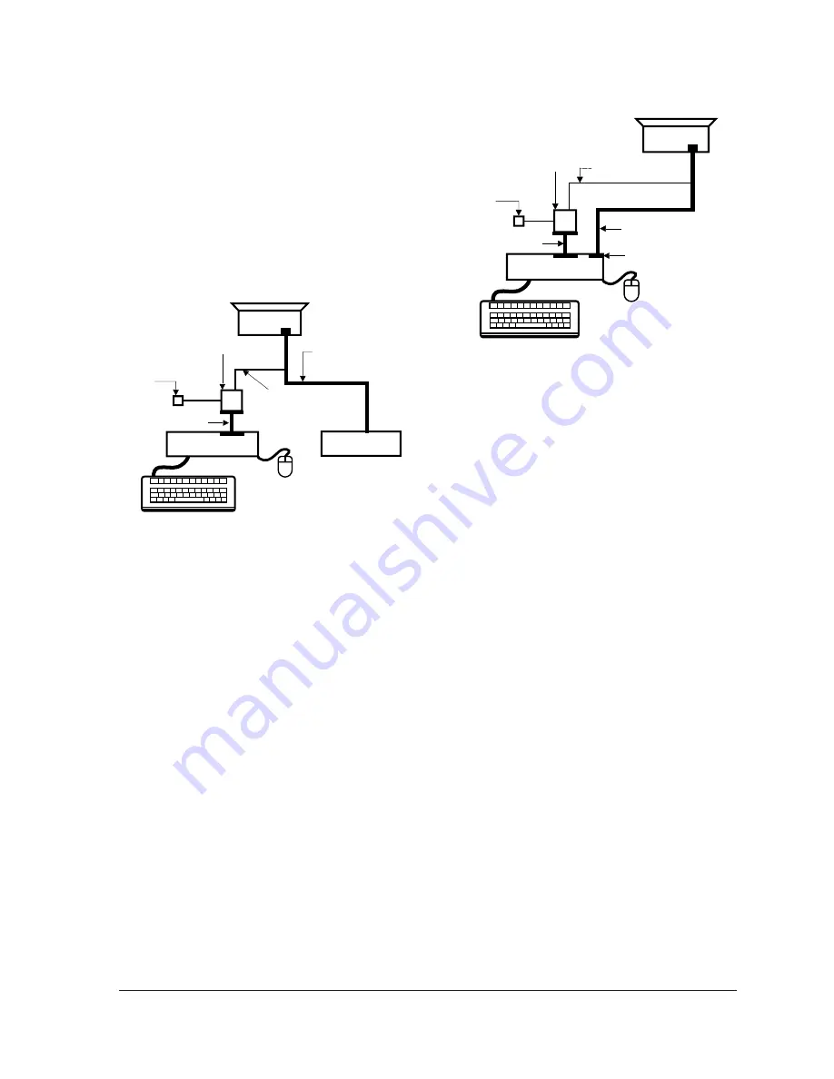
Connect the monitor to the signal generator and/
or PC as illustrated in Figures 4-1 and 4-2.
Note:
The signal cable connector which includes
the 3-wire cable must connect to the
monitor. If you use Setup 2 (PC only, no
signal generator) you can only make
adjustments to the signal timing available
on that computer system. To make
corrections to all factory timings requires
the use of an additional signal generator.
4 Alignment and Adjustments
4-2
TP17LT
MONITOR
INTERFACE
BOARD VER. 2.0
PC
SIGNAL
GENERATOR
3-WIRE
CABLE
SIGNAL CABLE
5V DC
ADAPTOR
PARALLEL CABLE
Figure 4-1. Setup 1, With Signal Generator
MONITOR
INTERFACE
BOARD VER. 2.0
PC
3-WIRE CABLE
SIGNAL CABLE
PARALLEL CABLE
D-SUB
CONNECTOR
5V DC
ADAPTOR
Figure 4-2. Setup 2, Without Signal Generator
Summary of Contents for TP17LT
Page 2: ...Samsung Electronics Co Ltd March 2000 Printed in Korea P N BH68 00129K 01 ...
Page 8: ...2 Product Specifications 2 4 TP17LT Memo ...
Page 37: ...6 Exploded View and Parts List 6 1 Front Cover CRT Ass y TP17LT 6 3 ...
Page 38: ...6 2 Chassis Stand Ass y 6 Exploded View Parts List 6 4 TP17LT ...
Page 39: ...6 3 Rear Cover Ass y 6 Exploded View Parts List TP17LT 6 5 ...
Page 40: ...Memo 6 Exploded View Parts List 6 6 TP17LT ...
Page 56: ...7 Electrical Parts List 7 16 TP17LT 7 3 Different Parts List CDT ...
Page 58: ...Memo 8 Block Diagrams 8 2 TP17LT ...
Page 59: ...TP17LT 9 1 9 Wiring Diagram ...
Page 60: ...10 1 TP17LT 10 Schematic Diagrams 10 1 SMPS Part Schematic Diagram ...
Page 62: ...10 Schematic Diagrams 10 3 TP17LT 10 2 Micom Part Schematic Diagram ...
Page 64: ...10 Schematic Diagrams 10 5 TP17LT 10 3 H V OSC Vertical Part Schematic Diagram ...
Page 66: ...10 Schematic Diagrams 10 7 TP17LT 10 4 Deflection Part Schematic Diagram ...
Page 68: ...10 Schematic Diagrams 10 9 TP17LT 10 5 Video Part Schematic Diagram ...


