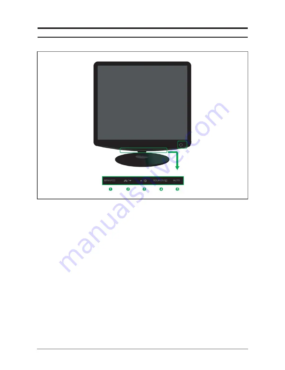
1. Menu button
Opens the OSD menu. Also use to exit the OSD
menu or return to the previous menu.
2. MagicBright button
MagicBright is a new feature providing optimum
viewing environment depending on the contents of
the image you are watching. Currently six different
modes are available: Custom, Text, Internet,
Game, Sport and Movie. Each mode has its own
pre-configured brightness value. You can easily
select one of six settings by simply pressing
MagicBright control buttons.
1) Custom
Although the values are carefully chosen by our
engineers, the pre-configured values may not be
comfortable to your eyes depending on your taste.
If this is the case, adjust the brightness and con-
trast by using the OSD menu.
2) Text
For documentations or works involving heavy text.
3) Internet
For working with a mixture of images such as text
and graphics.
4) Game
For watching motion pictures such as a game.
5) Sport
For watching motion pictures such as a sport.
6) Movie
For watching motion pictures such as a DVD or
Video CD.
7) Dynamic Contrast
Dynamic Contrast is to automatically detect distri-
bution of inputted visual signal and adjust to create
optimum contrast.
3. Brightness button
When OSD is not on the screen, push the button
to adjust brightness.
10 Operating Instructions and Installation
10-1
10 Operating Instructions and Installation
10-1 Front
Summary of Contents for SyncMaster 932BF
Page 6: ...10 Operating Instructions and Installation 10 4 Memo ...
Page 16: ...11 Disassembly and Reassembly 11 10 Memo ...
Page 23: ...12 PCB Layout 12 1 12 PCB Diagram 12 1 Main PCB Layout ...
Page 24: ...12 PCB Layout 12 2 Memo ...
Page 36: ...Memo 14 Reference Infomation 14 12 ...
Page 40: ...2 Product Specifications 2 4 Memo ...
Page 43: ...4 Troubleshooting 4 3 1 WAVEFORMS 2 3 ...
Page 45: ...4 Troubleshooting 4 5 1 WAVEFORMS 5 4 6 ...
Page 46: ...4 Troubleshooting 4 6 Memo ...
Page 55: ...7 Block Diagrams 7 1 7 Block Diagram 7 1 Power Tree ...
Page 56: ...7 Block Diagrams 7 2 7 2 Main Board Part ...
Page 57: ...7 3 IP Board Part SMPS Part 7 Block Diagrams 7 3 ...
Page 58: ...7 4 IP Board Part Inverter Part 7 Block Diagrams 7 4 ...
Page 62: ...1 Precautions 1 4 Memo ...
Page 69: ...13 Circuit Descriptions 13 7 13 3 IP BOARD Power Schematic Diagrams ...
Page 70: ...13 Circuit Descriptions 13 8 13 4 IP BOARD Inverter Schematic Diagrams ...
Page 72: ...9 Schematic Diagrams 9 2 1 2 3 4 5 6 ...
Page 74: ...8 Wiring Diagram 8 2 Memo ...


