background image


English     17


Français

Español

Deutsch

Italiano

English

Portuguese


Appendix


Troubleshooting


Before calling for service, check the information in this section to see if you can remedy any 
problems yourself.

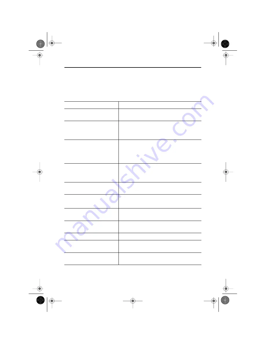
Table 3.  Troubleshooting problems 


Symptom

Corrective Actions


No Picture


Check to see that both the LCD Monitor and the 
computer are plugged in and turned on.

“No Connection,   
Check Signal Cable” appears


Check the signal cable connection between the 
computer and the LCD Monitor


Use the LCD Monitor self test described on page 8.

 “Video mode not supported”


Check the maximum resolution and the frequency 

on the video port of your computer.


Compare these values with the data in the preset 
timing modes, page 21. 

Picture is scrambled


Check the signal cable connection between the 
computer and LCD Monitor.


Perform Auto Adjustment (see page 6).

Picture is not clear


Adjust Fine and Coarse adjustments as needed (see 
page 13).

Picture is fuzzy


Perform LCD Monitor reset.


Eliminate accessories (i.e., video extension cables).

Picture bounces or has wavy 
oscillations


Check the signal cable connection between the 
computer and LCD Monitor.

Picture appears to be ghosting


Check the signal cable connection between the 
computer and LCD Monitor.

The image is too light or too dark


Adjust the Brightness and Contrast settings.

Color is not uniform


Adjust the color settings using the OSD COLOR 
menu.

The colors are distorted with dark 
or shadowed areas


Adjust the color settings using the OSD COLOR 
menu.

3_E70Sbody.fm  Page 17  Monday, August 13, 2001  10:18 AM

Summary of Contents for SyncMaster 70S

Page 1: ...USER S MANUAL 43cm 17 TFT LCD Monitor 70S 1_E70Scov fm Page 1 Thursday July 5 2001 3 33 PM ...

Page 2: ...ting auto adjustment function in display screen that is appeared as window termination button is pressed If there s still noise after automatic adjustment use FINE COARSE adjustment function Information in this document is subject to change without notice 2001 Samsung Electronics Co Ltd All rights reserved Reproduction in any manner whatsoever without the written permission of Samsung Electronics ...

Page 3: ... Windows 95 7 Self Test Feature Check STFC 8 Adjusting Your LCD Monitor 9 User Controls 9 Automatic Save 10 Direct Access Features 10 Brightness 10 Auto Adjustment 11 OSD Lock Unlock 11 On Screen Display OSD 12 Accessing the Menu System 12 Appendix 16 PowerSaver 16 Troubleshooting 17 Specifications 19 Pin Assignments 20 Display Modes 21 Changing the Stand 22 Removing the Stand 22 Attaching an Arm ...

Page 4: ...nitor to rain or use it near water in kitchens near swimming pools etc If the LCD Monitor accidentally gets wet unplug it and contact an authorized dealer immediately You can clean the LCD Monitor with a damp cloth when necessary but be sure to unplug the LCD Monitor first 9 Place the LCD Monitor on a solid surface and treat it carefully The screen is made of thin glass with a plastic front surfac...

Page 5: ...wing items are included with your monitor If any items are missing contact your dealer Manual Power Cord Monitor and Base 15 pin D Sub Signal Cable Diskette DC Adapter Warranty Card Not available in all locations Unpacking Your LCD Monitor 3_E70Sbody fm Page 3 Monday August 13 2001 10 18 AM ...

Page 6: ...ghtly below your eye level when you are comfortably seated Viewing angle Tilt the screen backward or forward to a comfortable viewing position Figure 1 Tilt the screen Kensington Security Slot This monitor offers you the opportunity to secure your monitor using a Kensington type security device Kensington lock not included Refer to your locking device documentation for installation instructions Fi...

Page 7: ...urn off your computer and unplug its power cord 2 Attach the blue signal cable connector to the video port on the back of your computer 3 Connect the power cord for your monitor to the power port on the power adapter 4 Plug the power cords of your computer and your monitor into a nearby outlet 5 Turn on your computer and monitor If your monitor displays an image installation is complete 6 Perform ...

Page 8: ...nnel DDC protocols so the PC system can automatically configure itself to use the LCD Monitor Auto Adjustment Even though your computer system can recognize your new LCD Monitor system the auto adjustment function will optimize the display settings for use with your computer Auto Adjustment can be accessed through the OSD see Image Lock on page 13 or use the direct access instructions below 1 Turn...

Page 9: ...ill start the Add New Hardware Wizard 2 Follow the same directions as given in the steps in the section above Windows 95 To determine the version of Windows 95 that your computer uses right click on the My Computer icon on the Windows desktop and select Properties The version number can be seen on the General section under System Follow the directions given below according to the version of your W...

Page 10: ... box with a red border and black text inside as shown in the following illustration Figure 4 Monitor self test screen The three boxes inside the border are red green and blue Failure of any of the boxes to appear indicates a problem with your monitor This box also appears during normal operation if the video cable becomes disconnected or damaged 4 Turn off your monitor and reconnect the video cabl...

Page 11: ...om the OSD while the OSD is displayed 3 Brightness Moves the selector between menus and sub menus on the OSD Decreases or increases values of the selected function Directly adjusts the brightness level if pressed while the OSD is off See the section on Direct Access Features on page 10 4 Menu Opens the OSD and sub menus Selects the highlighted function 5 Power button and Indicator light Turns the ...

Page 12: ...OSD disappears and the monitor does not save anything To exit without saving the changes you have made press the Exit button before the 2 seconds elapse Direct Access Features The features described in this section can be accessed quickly at the touch of one button Once you finish making adjustments to a feature push the Exit button to turn off the menu or allow the OSD to time out and disappear a...

Page 13: ...ing the same procedure 1 Push and hold the Menu button for 5 seconds to Lock or Unlock the controls When locked a LOCKED message displays Auto Adjustment Follow these instructions to enable or disable the automatic screen adjustments for your monitor 1 With the menu off push the Auto button The automatic adjustment display appears 2 Follow the directions previously given on page 6 25 Auto Adjustme...

Page 14: ... by that icon See the Menu adjustments table to view a complete list of all the functions available for the monitor 3 Push the Menu button once to activate the highlighted function then use the and buttons according to the indicators on the menu to make your changes 4 Push the Exit button once to return to the main menu to select another function or push the Exit button 1 or 2 times to exit from t...

Page 15: ...o your preference Use the buttons to adjust away interference If satisfactory results are not obtained using the Fine adjustment use the Coarse adjustment and then use Fine again This function may change the width of the display image Use the Horizontal function on the Position menu to center the display image on the screen Position Horizontal Vertical Position moves the viewing area around on the...

Page 16: ...rovides a scaling processor that can expand the addressability up to 1280 x 1024 Select the Normal setting to use the normal size viewing area for the current signal Expanded 1 expands the viewing area to the full width of the monitor screen Expanded 2 extends the viewing area both horizontally and vertically to the full size of the monitor screen Menu Effect Half Tone On Off Half Tone changes the...

Page 17: ...opens it displays in the same location on the screen Menu Position controls that location Menu Display Time 5 Seconds 10 Seconds 20 Seconds 200 Seconds The OSD stays active for as long as it is in use Menu Display Time sets the length of time the OSD will remain active after the last time you pushed a button Display Mode Select this icon to view the current user mode This screen only displays info...

Page 18: ...s occurs when you move the computer s mouse or press a key on the keyboard This monitor is EPA ENERGY STAR compliant and NUTEK compliant when used with a computer equipped with VESA DPMS functionality For energy conservation turn your monitor OFF when it is not needed or when leaving it unattended for long periods State Normal Operation Power Saving Function mode EPA NUTEK Standby Mode Sleep Mode ...

Page 19: ...e data in the preset timing modes page 21 Picture is scrambled Check the signal cable connection between the computer and LCD Monitor Perform Auto Adjustment see page 6 Picture is not clear Adjust Fine and Coarse adjustments as needed see page 13 Picture is fuzzy Perform LCD Monitor reset Eliminate accessories i e video extension cables Picture bounces or has wavy oscillations Check the signal cab...

Page 20: ...nce The LCD Monitor is saving your changes to the OSD The power indicator is blinking amber The LCD Monitor is using its power management system Check the power management utility on your computer Cannot adjust LCD Monitor with the buttons on the front panel Please contact customer service You need the monitor driver software You can download the driver from the internet at http www samtron com Ta...

Page 21: ...ion Input Signal Terminated Analog video 0 7 Vpp positive at 75 Ω Separate sync composite and sync on green Maximum Pixel Clock 135 MHz Power Adapter AC 90 264 Volts 60 Hz 50 Hz 3 Hz Power Consumption 42 W Maximum 40 W Nominal Dimensions Weight W x D x H 440 x 182 x 462 mm 7 9 kg 17 32 x 7 16 x 18 19 in 17 41 lbs All measurements approximate VESA Mounting Interface 100 mm x 100 mm For use with Spe...

Page 22: ...No 15 Pin Side of the Signal Cable Pin No 15 Pin Side of the Signal Cable 1 2 3 4 5 6 7 8 Red Green Blue GND GND DDC Return GND R GND G GND B 9 10 11 12 13 14 15 NC GND Sync Self test GND DDC Data H Sync V Sync DDC Clock 3_E70Sbody fm Page 20 Monday August 13 2001 10 18 AM ...

Page 23: ...play modes listed below the screen image has been optimized during manufacture Table 6 Preset timing modes Display Mode Horizontal Frequency kHz Vertical Frequency Hz Pixel Clock MHz Sync Polarity H V 720 x 400 31 469 70 087 28 322 640 x 480 31 469 59 940 25 175 640 x 480 37 500 75 000 31 500 640 x 480 43 269 85 008 36 000 800 x 600 46 875 75 000 49 500 800 x 600 53 674 85 061 56 250 1024 x 768 48...

Page 24: ... protect the screen 3 Pull the cable covers off the back of your monitor Grasp the top of the stand cover a and pull the cover out then up to remove it Using both hands release the tab on each side of the hinge cover b then pull the cover out and off the monitor 4 Remove the four screws and then remove the Stand from the LCD Monitor 3_E70Sbody fm Page 22 Monday August 13 2001 10 18 AM ...

Page 25: ...onitor cabinet except for gaining access to the cable connectors as described on page 6 Users cannot service the monitor User maintenance is restricted to cleaning as explained below Unplug the monitor from the power outlet before cleaning To clean your LCD Monitor screen lightly dampen a soft clean cloth with water or mild detergent If possible use a special screen cleaning tissue or solution sui...

Page 26: ...driver 6 Image effect 14 Image lock 13 Image size 14 K Kensington security slot 4 M MENU 9 Menu display time 15 Menu position 15 O On Screen Display OSD 12 OSD Lock Unlock 11 P Pin Assignments 20 Plug and play 6 Position 13 Power button 9 Preset timing modes 21 R Reset 14 S Self Test Feature Check 8 Sleep mode 16 Standby mode 16 Specifications 19 STFC 8 T Tilt the screen 4 Troubleshooting 17 INDEX...

Page 27: ... for products Marked with FCC Logo This device complies with Part 15 of the FCC Rules Operation is subject to the following two conditions 1 this device may not cause harmful interference and 2 this device must accept any interference received including interference that may cause undesired operation The party responsible for product compliance SAMSUNG ELECTRONICS CO LTD America QA Lab of samsung ...

Page 28: ...U KU TOKYO 103 JAPAN Tel 81 3 5641 9860 Fax 81 3 5641 9861 SAMTRON SWEDEN SAMSUNG ELECTRONICS SVENSKA AB BOX 713 S 194 27 UPPLANDS VASBY Tel 468 590 966 00 Fax 468 590 966 50 SAMTRON MEXICO SAMSUNG ELECTRONICS MEXICO S A DE C V Mina No 200 ESQ GAVILANCOL GUADALUPE DEL MORAL IZTAPALAPA MEXICO D F C P 09300 Tel 525 686 0800 Fax 525 686 5094 P N BN68 00202B 02 As an ENERGY STAR Partner SAMSUNG has de...

Reviews: