background image

   ,   

 ENTER

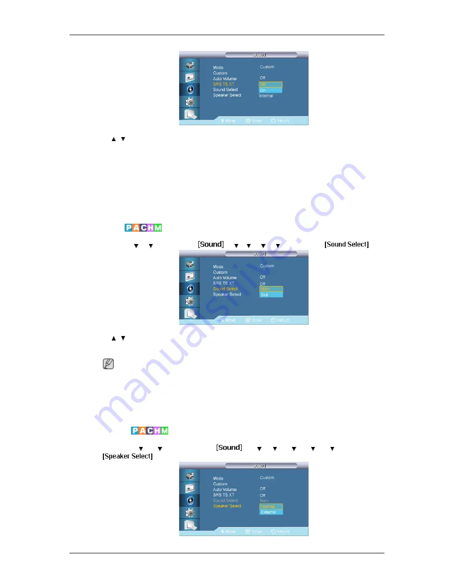
SRS TS XT

 is a patented SRS technology that solves the problem of playing 5.1 multichannel

content over two speakers. TruSurround XT delivers a compelling, virtual surround sound
experience through any two-speaker playback system, including internal television speakers.
It is fully compatible with all multichannel formats.

1.

Off

2.

On

Sound Select 

MENU 


 ENTER 


 ENTER 


   ,   

 ENTER

Selects either Main or Sub when 

PIP

 is 

On

.

 Note

Available Modes: 

PIP ON

1.

Main

2.

Sub

Speaker Select 

MENU 


 ENTER 


 ENTER 

Adjusting the LCD Display

Summary of Contents for SyncMaster 400UXN-2

Page 1: ...SyncMaster 400UX 2 400UXN 2 460UX 2 460UXN 2 LCD Display User Manual ...

Page 2: ...d to prevent an electric shock Power When not used for extended period of time set your computer to DPM If using a screen saver set it to active screen mode The images here are for reference only and are not applicable in all cases or countries Shortcut to Anti Afterimage Instructions Do not use a damaged power cord or plug or a damaged or loose power outlet Otherwise this may result in electric s...

Page 3: ...ided power cord of another product Otherwise this may result in fire or electric shock Installation Be sure to contact an authorized Service Center when installing your monitor in a location with heavy dust high or low temperatures high hu midity and exposed to chemical substances and where it operates for 24 hours such as at airports train stations etc Failure to do so may cause serious damage to...

Page 4: ...ure that there is a clearance of more than 4 inches 10 cm from the wall Otherwise it may result in fire due to an increase in the internal temperature Ensure that the packaging vinyl is kept away from children Otherwise it may result in serious harm suffocation if children play with it If the height of your monitor is adjustable do not place any ob ject or part of your body on the stand when lower...

Page 5: ...using it When cleaning the product do not spray water directly onto the main body of the product Ensure that water does not enter the product and that it is not wet Otherwise this may result in electric shock fire or a malfunc tion Others The product is a high voltage product Do not disassemble re pair or modify the product yourself Otherwise this may result in electric shock or fire If the produc...

Page 6: ...ial enters the product disconnect the power cord and contact a Service Center This may result in a product malfunction electric shock or fire Do not use or keep combustible spray or flammable material near the product Otherwise this may result in an explosion or fire Do not insert any metal such as chopsticks coins pins and steel or flammable objects such as matches or paper inside the product thr...

Page 7: ... power outlet Otherwise this may result in overheating or fire due to dust and may result in fire due to electric shock or leakage Do not place any heavy items or toys or confectionery such as cookies etc that may attract the attention of children and to the product Your children may hang onto the product causing it to fall and this may result in personal injury or death Be careful that children d...

Page 8: ...Do not use a humidifier near the product Otherwise this may result in electric shock or fire When there is a gas leak do not touch the product or the power plug ventilate immediately If a spark occurs it may cause an explosion or fire If the product has been turned on for a long time the display panel becomes hot Do not touch it Keep the small accessories in a location out of the reach of chil dre...

Page 9: ...Do not put any heavy objects on the product This may result in personal injury and or damage to the prod uct Safety Instructions ...

Page 10: ...ents of the Package Remove the lock from the package box as shown in the figure above Lift up the package box by holding the grooves on both sides of the package box Check the contents of the package Remove the Styrofoam and vinyl cover Note After unpacking the package make sure to check the contents of the package Make sure to keep the package box for transporting the product in the future Unpack...

Page 11: ...CD MagicInfo Manual CD Applicable to the UXN 2 model only Cables Power Cord Others Remote Control BP59 00138A Batteries AAA X 2 Not available in all loca tions BNC to RCA Adaptor Jack Applicable to the UX 2 model only Sold separately D Sub Cable DVI Cable LAN Cable Used with UXN 2 model only Introduction ...

Page 12: ...so use to exit the OSD menu or return to the previous menu Navigate buttons Up Down buttons Moves from one menu item to another vertically or adjusts selected menu values Adjust buttons Left Right buttons Volume buttons Moves from one menu item to another horizontally or adjusts selected menu values When OSD is not on the screen press the button to adjust volume ENTER button ENTER Activates a high...

Page 13: ...f Brightness Sensor Optional Automatically detects the surrounding brightness it accordingly Note This function is activated only on the models equipped with an auto bright ness sensor Power indicator Shows PowerSaver mode by blinking green Note See PowerSaver described in the manual for further information regarding power saving functions For energy conservation turn your LCD Display OFF when it ...

Page 14: ...232C Serial PORT MDC Multiple Display Control Program Port RGB COMPONENT IN PC COMPO NENT Connection Terminal Input Use a D Sub Cable 15 pin D Sub PC mode Analog PC Connect the RGB COMPONENT IN port on the monitor to the COMPONENT port on the external device using the D SUB to COMPONENT cable Connect the RGB COMPONENT IN port on the monitor to the BNC port on the PC using the D SUB to BNC cable In...

Page 15: ... the monitor to the HDMI IN port on the other monitor using the DVI to HDMI cable DVI HDMI and network signals sent via the DVI OUT port are displayed on the second display which has the DVI IN port Note Up to 6 Full HD or 10 HD monitors can be connected May differ depending on the product AV IN VIDEO Connect the VIDEO terminal of your mon itor to the video output terminal of the exter nal device ...

Page 16: ...dation up to 10 LCD Displays can be connected May not be supported depending on the connected cable Note Applicable to the UX 2 model only BNC Component Connection Terminal input During component input please check spec ifications for the input ports below R Y G PB B PR H V R Y Red port input G PB Green port input B PR Blue port input Note Applicable to the UX 2 model only RGB OUT Note Applicable ...

Page 17: ...e purchased separately Note The location of the Kensington Lock may be different depending on the model Using the Anti Theft Kensington Lock 1 Insert the locking device into the Ken sington slot on the LCD Display and turn it in the locking direction 2 Connect the Kensington Lock cable 3 Fix the Kensington Lock to a desk or a heavy stationary object Note See Connecting Cables for further informati...

Page 18: ...L GUIDE but ton The button is used to select Digital channels Electronic Program Guide EPG display This function does not work for this LCD Display 5 VOL Adjusts the audio volume 6 SOURCE Press the button to change the input signal SOURCE Changing the SOURCE is only allowed for external devices that are connected to the LCD Display at the time 7 D MENU DTV menu display This function does not work ...

Page 19: ...ult FM Stereo Mono Mono Manual Change Stereo Mono Stereo SAP Mono SAP Mono DUAL STEREO MONO DUAL l DUAL ll and MONO NICAM MONO NICAM STEREO can be operated depending on the broadcasting type by using the DUAL button on the remote control while watching TV 14 ENTER PRE CH This button is used to return to the immediately previous channel This function does not work for this LCD Display 15 MUTE Pause...

Page 20: ...20 EXIT Exits from the menu screen 21 MagicInfo MagicInfo Quick Launch Button Introduction ...

Page 21: ...n connecting AV input devices refer to the contents under Adjusting Your LCD Display 400UXN 2 460UXN 2 400UX 2 460UX 2 There are several ways to connect the computer to the monitor Choose one from the following options Using the D sub Analog connector on the video card Connect the D sub to the 15 pin RGB port on the back of your LCD Display and the 15 pin D sub Port on the computer ...

Page 22: ...e graphics card Connect the HDMI IN port on the monitor to the HDMI port on the PC using the HDMI cable Note When the HDMI cable to the PC ensure that you select HDMI from both the Source List and Edit Name before selecting PC or DVI device so that normal PC screen and sound can be outputted Note that sound is only available when connected according to the option that follows Connections ...

Page 23: ...the LCD Display Turn on the power switch Note Turn on both your computer and the LCD Display Contact a local SAMSUNG Electronics Service Center to buy optional items Connecting to Other devices Note AV input devices such as DVD players VCRs or camcorders as well as your computer can be connected to the LCD Display For detailed information on connecting AV input devices refer to the contents under ...

Page 24: ... R Y G PB B PR ports on the monitor to the BNC port on the external device using the BNC to BNC cable 2 Select BNC for the Camcorder connection using the Source button on the front of the LCD Display or on the remote control Note Applicable to the UX 2 model only Connecting a DVD Player Applicable to the UX 2 model only 1 Connect a set of audio cables between the AV COMPONENT AUDIO IN L AUDIO R on...

Page 25: ...deo consult your DVD manual Connecting using a Component Cable 1 Connect a set of audio cables between the AV COMPONENT AUDIO IN L AUDIO R on the LCD Display and the AUDIO OUT jacks on the DVD player or other external device 2 Connect the Component D sub cable to the RGB COMPONENT IN ports on the monitor Note Select Component using the SOURCE button on the front of the LCD Display or on the remote...

Page 26: ...e AV IN VIDEO on the LCD Display 3 Select AV for the Camcorder connection using the Source button on the front of the LCD Display or on the remote control 4 Then start the Camcorder with a tape inserted Note The audio video cables shown here are usually included with a Camcorder If not check your local electronics store If your camcorder is stereo you need to connect a set of two cables Connecting...

Page 27: ...input port on another monitor using a DVI cable 2 Connect between the AUDIO OUT port on the LCD Display and the audio input port on another monitor using a stereo cable 3 Select DVI using the SOURCE button on the front of the LCD Display or on the remote control Note DVI OUT does not support HDCP Connecting Using a DVI to HDMI Cable Connections ...

Page 28: ...ellite Box Applicable to the UX 2 model only 1 Connect a Component cable between the BNC COMPONENT IN R Y G PB B PR port on the LCD Display and the PR Y PB jacks on the Set Top Box 2 Connect a set of audio cables between the AV COMPONENT AUDIO IN L AUDIO R on the LCD Display and the AUDIO OUT jacks on the Set Top Box Note Select Component for the connection to a DTV Set Top Box using the SOURCE bu...

Page 29: ...an explanation of Component video see your Set Top Box owner s manual Connecting to an Audio System 1 Connect a set of audio cables between the AUX L R jacks on the AUDIO SYSTEM and AUDIO OUT on LCD Display Connecting a LAN Cable Note AV input devices such as DVD players VCRs or camcorders as well as your computer can be connected to the LCD Display For detailed information on connecting AV input ...

Page 30: ...Connect the LAN cable Note Applicable to the UXN 2 model only Connecting a USB device Note You can connect USB devices such as a mouse or keyboard Applicable to the UXN 2 model only Connections ...

Page 31: ...e oper ating system you have Prepare a blank disk and download the driver program file at the Internet web site shown here Internet web site http www samsung com Installing the Monitor Driver Automatic 1 Insert CD into the CD ROM drive 2 Click Windows 3 Choose your monitor model in the model list then click the OK button 4 If you can see following message window then click the Continue Anyway butt...

Page 32: ...oft Windows Vista Operating System 1 Insert your Manual CD into your CD ROM drive 2 Click Start and Control Panel Then double click on Appearance and Personal ization 3 Click Personalization and then Display Settings 4 Click Advanced Settings 5 Click Properties in the Monitor tab If the Properties button is deactivated it means the configuration for your monitor is completed The monitor can be use...

Page 33: ...ge your system The certified driver will be posted on Samsung Monitor homepage 6 Click Update Driver in the Driver tab 7 Check the Browse my computer for driver software checkbox and click Let me pick from a list of device drivers on my computer 8 Click Have Disk and select the folder for example D Drive where the driver setup file is located and click OK Using the Software ...

Page 34: ...l that matches your monitor from the list of monitor models on the screen and click Next 10 Click Close Close OK OK on the following screens displayed in sequence Microsoft Windows XP Operating System Using the Software ...

Page 35: ... Click Display icon and choose the Settings tab then click Advanced 4 Click the Properties button on the Monitor tab and select Driver tab 5 Click Update Driver and select Install from a list or then click Next button 6 Select Don t search I will then click Next and then click Have disk Using the Software ...

Page 36: ...wing message window then click the Continue Anyway button Then click OK button Note This monitor driver is under certifying MS logo and this installation will not damage your system The certified driver will be posted on Samsung Monitor homepage http www samsung com 9 Click the Close button then click the OK button continually Using the Software ...

Page 37: ... Choose Monitor Case1 If the Properties button is inactive it means your monitor is properly configured Please stop installation Case2 If the Properties button is active click the Properties button then follow the next steps 5 Click Driver and then click on Update Driver then click on the Next button 6 Choose Display a list of the known drivers for this device so that I can choose a specific drive...

Page 38: ...gue box Microsoft Windows NT Operating System 1 Click Start Settings Control Panel and then double click Display icon 2 In Display Registration Information window click Settings Tab and then click All Display Modes 3 Select a mode that you wish to use Resolution Number of colors and Vertical frequency and then click OK 4 Click Apply button if you see the screen working normally after clicking Test...

Page 39: ...n file Note If the popup window to install the software for the main screen is not displayed proceed with the installation using the MDC executable file on the CD 3 When the Installation Shield Wizard window appears click Next 4 Select I agree to the terms of the license agreement to accept the terms of use 5 Click Install 6 The Installation Status window appears 7 Click Finish 8 When the installa...

Page 40: ...move Programs option of the Windows Control Panel Perform the following steps remove MDC Select Setting Control Panel on the Start menu and then double click Add Delete a pro gram Select MDC from the list and then click the Add Delete button Using MDC Using the Software ...

Page 41: ...C a standard of serial communication is used for the communication between a PC and a display Therefore a serial cable should be connected between the serial port on a PC and the serial port on a display Main Screen Click Start Program Samsung MDC System to start the program Select a set to see the volume of the selected set within the slider ...

Page 42: ...ng for the PC Serial Port can change The original value is COM1 5 Click Select all or Clear to select or clear all displays 6 Use Grid to view brief information on selected display 7 Select a display from Display Selection 8 Use Control Tools to control displays Note The remote control Enable Disable function operates whether or not the power is On Off and this applies to all displays connected to...

Page 43: ...n the Port Selection Menu 3 If the exact port name that is connected to the LCD Display using a serial cable is not selected communication will be unavailable 4 The selected port is stored in the program and used for the next program as well Power Control 1 Click Power Control of the main icons and the Power Control screen appears ...

Page 44: ...Info Grid shows some basic information necessary to Power Control 1 Power Status 2 Input 3 Image Size 4 On Timer 5 Off Timer 2 Use the Select All button or Check Box to choose a display to control ...

Page 45: ...ff the Mute function of the selected display When selecting one set at a time turn on the Mute function for the selected set The Mute function is disabled automatically when you adjust the volume level The values return to the default settings when you undo the selections or choose Select All The Power Control feature is available for all displays The Volume Control and Mute features are available...

Page 46: ... PC Mode ...

Page 47: ... of the selected display to DTV 6 AV Changes the Input Source of the selected display to AV 7 S Video Changes the Input Source of the selected display to S Video 8 Component Changes the Input Source of the selected display to Component 9 MagicInfo The Input source of MagicInfo works only on MagicInfo model 10 HDMI Changes the Input Source of the selected display to HDMI 11 Channel Channel arrow ap...

Page 48: ...the current Image Size of the display in use 3 Input Info Grid displays only the displays whose Input Source is PC BNC DVI 4 PC Source When you click Image Size the PC Source tab first appear The Image Size Control button controls Image Size available for PC BNC DVI 5 Video Source Click the Video Source tab to control Image Size for respective Input Source The Input source of MagicInfo works only ...

Page 49: ... AV S Video Component or DVI HDCP as input source 3 Switch Image Size of the selected display randomly Note Auto Wide Zoom1 and Zoom2 are not available for selection when the input signal type for Component and DVI HDCP is 720p or 1080i The Auto Wide mode is available only for TV AV and S Video 4 The screen modes can only be adjusted when a TV PAL only is connected and the Image Size item is set t...

Page 50: ...tatus Source Volume of the selected display 3 Off Time Setup Set the Hour Minute and AM PM Status for Off Time Setup of the selected display 4 Shows the On Time settings 5 Shows the Off Time settings The Input source of MagicInfo works only on MagicInfo model The Input source of TV works only on TV model Time Control is available only for the displays for which the power status is ON At On Time Se...

Page 51: ...isplay and changes the size to Large 4 Small Turns on the PIP of the selected display and changes the size to Small 5 Double 1 Turns on the PIP of the selected display and changes the size to Double 1 6 Double 2 Turns on the PIP of the selected display and changes the size to Double 2 7 Double 3 Picture By Picture Turns on the PBP of the selected display and changes the size to Double 3 The Input ...

Page 52: ...selected display to DVI 5 AV Changes the source of the PIP of the selected display to AV 6 S Video Changes the source of the PIP of the selected display to S Video 7 Component Changes the source of the PIP of the selected display to Component 8 HDMI Changes the source of the PIP of the selected display to HDMI Note Some of the PIP Sources may not be available for selection depending on the input s...

Page 53: ... and displays it on the slide bar When Select All is chosen the default value is displayed Changing a value in this screen will automatically change the mode to CUSTOM 1 Picture Available only for TV AV S Video Component HDMI DTV 2 Contrast Adjusts Contrast of the selected display 3 Brightness Adjusts Brightness of the selected display 4 Sharpness Adjusts Sharpness of the selected display 5 Color ...

Page 54: ...ailable only for the displays whose power status is ON and if no selection is made the factory default is displayed Settings Picture PC 1 Click Settings of the main icons and the Settings Control screen appears Info Grid shows some basic information necessary to Settings Control When each function is selected the set value of the selected function is displayed in the slide When selected each funct...

Page 55: ...or Temp Adjusts the Color Temp for the selected display 9 Brightness Sensor Adjusts the Brightness Sensor for the selected display 10 Dynamic Contrast Adjusts the Dynamic Contrast for the selected display The Input source of MagicInfo works only on MagicInfo model The Input source of TV works only on TV model Color Temp is only enabled if the Color Tone is set to Off This feature is available only...

Page 56: ... mode to CUSTOM 1 Audio Controls audio settings for all input sources 2 Bass Adjusts Bass of the selected display 3 Treble Adjusts Treble of the selected display 4 Balance Adjusts Balance of the selected display 5 SRS TS XT SRS TS XT Sound ON OFF of the selected display 6 Sound Select Select either Main or Sub when PIP is On The Input source of MagicInfo works only on MagicInfo model The Input sou...

Page 57: ...Adjusts Fine of the selected display 4 Position Adjusts Position of the selected display 5 Auto Adjustment Self Adjust to the incoming PC signal The Input source of MagicInfo works only on MagicInfo model The Input source of TV works only on TV model Settings Control is available only for the displays for which the power status is ON Maintenance Lamp Control 1 Click on the Maintenance icon in the ...

Page 58: ...mp Control 3 Manual Lamp Control Allows you to adjust the backlight of the selected display regardless of the time The Auto Lamp Control automatically turns off if you adjust using the Manual Lamp Control The Maintenance Control feature is available only for the displays whose power status is ON The Input source of MagicInfo works only on MagicInfo model The Input source of TV works only on TV mod...

Page 59: ...me when the Safety Screen function must be performed The Type item can be set to Scroll Pixel Bar Eraser All White or Pattern 4 Safety Screen2 This function is used to prevent afterimages from occurring There are five 5 types that you can select and control with this function For the Scroll type the Time item can be set to 1 2 3 4 or 5 For the Bar and Eraser types it can be set to 10 20 30 40 or 5...

Page 60: ...Wall Screen divider The screen can be divided into You can select a number of screens with a different layout when dividing z Select a mode from Screen divider z Select a display from Display Selection z The place will be set up by pressing a number in the selected mode z The MDC program supplied by Samsung supports up to 5x5 LCD Displayes 3 On Off Turns on off the Video Wall function of the selec...

Page 61: ...ot appear on the other Control Info Grids Check to see if the display power is ON You can check this in Power Control Info Grid Check if you can change the input source of the display 3 The dialogue box appears repeatedly Check to see if the display you wish to control is selected 4 Both On Timer and Off Timer have been set but different time is showing Apply current time to synchronize the displa...

Page 62: ... value for the selected display 3 Selected one display ID1 and add another display ID3 The program which was displaying the settings value of ID 1 fetches and displays the value of ID3 4 Selected all sets using Select All Returns to the Factory Default Value ...

Page 63: ...not be activated on the UXN 2 model MagicInfo supports the UXN 2 model only Source List MENU ENTER ENTER ENTER Use to select PC DVI or other external input sources connected to the LCD Display Use to select the screen of your choice 1 PC 2 DVI 3 AV 4 Component 5 HDMI 6 MagicInfo PIP Note Available Modes PIP ON ...

Page 64: ...R Note More than one PIP cannot be overlapped on screen as BNC and the Component use the same terminal If you select in Size Position and Transparency will not be activated PIP MENU ENTER ENTER ENTER ENTER Turns the PIP Screen Off On Off On Source MENU ENTER ENTER ENTER ENTER Selects the input source for the PIP PC DVI AV Component HDMI BNC DVI AV HDMI DVI AV PC BNC Component PC Adjusting the LCD ...

Page 65: ...PIP window will appear on the main screen and the main screen image will appear in the PIP window Size MENU ENTER ENTER ENTER ENTER Changes the Size of the PIP window Position MENU ENTER ENTER ENTER ENTER Changes the Position of the PIP window Transparency MENU ENTER ENTER ENTER Adjusting the LCD Display ...

Page 66: ...VD Cable STB HD STB Satellite STB AV Receiver DVD Receiver Game Camcorder DVD Combo DHR PC BNC HDMI Component AV DVI Note The displayed devices differ depending on the external input mode When connecting a PC to the HDMI or DVI terminal set Edit Name to PC In other cases set Edit Name to AV However since 640x480 720P 1280x720 and 1080p 1920x1080 are common signals for AV and PC make sure to set th...

Page 67: ...he con tents of the image you are watching Currently four different modes are available Enter tain Internet Text and Custom Each mode has its own pre configured brightness value Not available when Dynamic Contrast is set to On 1 Entertain High brightness For watching motion pictures such as from a DVD or VCR 2 Internet Medium brightness For working with a mixture of images such as texts and graphi...

Page 68: ...ontrast and brightness can be changed to your personal preference MENU ENTER ENTER Not available when Dynamic Contrast is set to On Note By adjusting the picture using the Custom function MagicBright will change to Custom mode Contrast MENU ENTER ENTER ENTER ENTER Adjusts the Contrast Brightness MENU ENTER ENTER ENTER ENTER Adjusts the Brightness Sharpness MENU ENTER ENTER ENTER ENTER Adjusts the ...

Page 69: ...on is disabled If you set the Color Tone to Off the Color Control function is disabled Color Control Adjusts individual Red Green Blue color balance MENU ENTER ENTER Not available when Dynamic Contrast is set to On Note If you adjust the picture by using the Color Control function Color Tone will turn to the Custom mode Red MENU ENTER ENTER ENTER ENTER Green MENU ENTER ENTER ENTER Adjusting the LC...

Page 70: ...get the best image by removing noise that creates unstable images with jitters and shakiness If satisfactory results are not obtained using the Fine adjustment use the Coarse adjustment and then use Fine again Available in PC mode only MENU ENTER ENTER Coarse MENU ENTER ENTER ENTER ENTER Removes noise such as vertical stripes Coarse adjustment may move the screen image area You may relocate it to ...

Page 71: ...ly and vertically Auto Adjustment MENU ENTER ENTER The values of Fine Coarse Position are adjusted automatically By changing the resolution in the control panel the auto function is performed Available in PC mode only Signal Balance This is used to make up for the weak RGB signal transmitted by a long signal cable MENU ENTER ENTER Available in PC mode only Signal Balance MENU ENTER ENTER ENTER Adj...

Page 72: ...ENTER ENTER ENTER 1 R Gain MENU ENTER ENTER ENTER ENTER ENTER 2 G Gain MENU ENTER ENTER ENTER ENTER ENTER 3 B Gain MENU ENTER ENTER ENTER ENTER ENTER 4 R Offset MENU ENTER ENTER ENTER ENTER ENTER 5 G Offset MENU ENTER ENTER ENTER ENTER ENTER 6 B Offset Adjusting the LCD Display ...

Page 73: ...th a DVD or set top box connecting to the product via HDMI or DVI image quality deterioration black level lower quality contrast lighter color tone etc may occur depending on the connected external device 1 Normal 2 Low Note For Timing which can be used for both the PC and the DTV in DVI HDMI mode HDMI Black Level will be activated Adjusting the LCD Display ...

Page 74: ...e Contrast of the PIP window on the screen 2 Brightness MENU ENTER ENTER ENTER ENTER Adjusts the Brightness of the PIP window on the screen 3 Sharpness MENU ENTER ENTER ENTER ENTER Adjusts the Sharpness of the PIP window on the screen 4 Color MENU ENTER ENTER ENTER ENTER Adjusts the Color of the PIP window on the screen Adjusting the LCD Display ...

Page 75: ...is NTSC Dynamic Contrast MENU ENTER ENTER ENTER Dynamic Contrast automatically detects the distribution of the visual signal and adjusts to create an optimum contrast 1 Off 2 On Lamp Control MENU ENTER ENTER ENTER Adjusts the inverter lamp in order to reduce energy consumption Note This function does not operate when Dynamic Contrast is set to On in PC DVI AV HDMI Component or MagicInfo modes Magi...

Page 76: ... four automatic picture settings Dynamic Standard Movie and Custom that are preset at the factory Dynamic Standard Movie or Custom can be activated Not available when Dynamic Contrast is set to On 1 Dynamic 2 Standard 3 Movie 4 Custom Custom By using the on screen menus the contrast and brightness can be changed to your personal preference MENU ENTER ENTER Not available when Dynamic Contrast is se...

Page 77: ... ENTER ENTER Adjusts the Brightness Sharpness MENU ENTER ENTER ENTER ENTER Adjusts the picture Sharpness Color MENU ENTER ENTER ENTER ENTER Adjusts the picture Color Tint MENU ENTER ENTER ENTER ENTER Adds a natural tone to the display Color Tone MENU ENTER ENTER Adjusting the LCD Display ...

Page 78: ... 5 Warm1 6 Warm2 Note If you set the Color Tone to Cool2 Cool1 Normal Warm1 or Warm2 the Color Temp function is disabled Color Temp MENU ENTER ENTER ENTER Color temp is a measure of the warmth of the image colors Not available when Dynamic Contrast is set to On Note This function is only enabled if the Color Tone is set to Off Size MENU ENTER ENTER Adjusting the LCD Display ...

Page 79: ...is set to On Note Certain external devices may feed the display an out of spec signal that may cause cutoff even when using the Screen Fit feature Zoom 1 Zoom 2 are unavailable in HDMI mode The Position and Reset functions are available in Zoom 1 or Zoom 2 modes Digital NR Digital Noise Reduction MENU ENTER ENTER ENTER Turns the Digital Noise Reduction feature Off On The Digital Noise Reduction fe...

Page 80: ...by configuring the HDMI black level 1 Normal 2 Low Note For Timing which can be used for both the PC and the DTV in DVI HDMI mode HDMI Black Level will be activated Film Mode MENU ENTER ENTER ENTER The Film Mode feature offers you a theater quality viewing experience In HDMI mode this function is available when the input signal is interlaced scan it is not available is progressive scan 1 Off 2 On ...

Page 81: ...usts the Brightness of the PIP window on the screen 3 Sharpness MENU ENTER ENTER ENTER ENTER Adjusts the Sharpness of the PIP window on the screen 4 Color MENU ENTER ENTER ENTER ENTER Adjusts the Color of the PIP window on the screen Note Enabled only when the PIP input is selected in AV HDMI or Component mode 5 Tint MENU ENTER ENTER ENTER Adjusting the LCD Display ...

Page 82: ...detects the distribution of the visual signal and adjusts to create an optimum contrast 1 Off 2 On Lamp Control MENU ENTER ENTER ENTER Adjusts the inverter lamp in order to reduce energy consumption Note This function does not operate when Dynamic Contrast is set to On in PC DVI AV HDMI Component or MagicInfo modes MagicInfo Applicable to the UXN 2 model only Sound Available Modes PC DVI BNC AV Co...

Page 83: ...s or concerts 3 Movie Selects Movie when viewing movies 4 Speech Selects Speech when watching a show that is mostly dialog i e news 5 Custom Selects Custom if you want to adjust the settings according to your personal preferen ces Custom The sound settings can be adjusted to suit your personal preferences MENU ENTER ENTER Note You can hear the sound even when sound value is set to 0 If you adjust ...

Page 84: ... frequency audio Balance MENU ENTER ENTER ENTER ENTER Allows you to Adjusts the sound balance between the left and right speakers Auto Volume MENU ENTER ENTER ENTER Reduces the difference in volume control between broadcasters 1 Off 2 On SRS TS XT MENU ENTER ENTER Adjusting the LCD Display ...

Page 85: ...ling virtual surround sound experience through any two speaker playback system including internal television speakers It is fully compatible with all multichannel formats 1 Off 2 On Sound Select MENU ENTER ENTER ENTER Selects either Main or Sub when PIP is On Note Available Modes PIP ON 1 Main 2 Sub Speaker Select MENU ENTER ENTER Adjusting the LCD Display ...

Page 86: ... speaker 2 External When sound is only outputted from the External speakers the volume control is also only available from the External speakers Setup Available Modes PC DVI BNC AV Component HDMI MagicInfo Note The BNC mode will not be activated on the UXN 2 model MagicInfo supports the UXN 2 model only Language MENU ENTER ENTER ENTER You can choose one of 13 languages Note The language chosen aff...

Page 87: ...f Timer MENU ENTER ENTER Clock Set MENU ENTER ENTER ENTER ENTER Current Time Setting Sleep Timer MENU ENTER ENTER ENTER ENTER Turns the LCD Display off automatically at certain times 1 Off 2 30 3 60 4 90 5 120 6 150 7 180 On Timer MENU ENTER ENTER ENTER Adjusting the LCD Display ...

Page 88: ...el at the time the LCD Display turns on automatically Off Timer MENU ENTER ENTER ENTER ENTER Turns the LCD Display off automatically at a preset time Menu Transparency MENU ENTER ENTER ENTER Change the transparency of the background of the OSD 1 High 2 Medium 3 Low 4 Opaque Adjusting the LCD Display ...

Page 89: ...lay is 0000 Lock On MENU ENTER ENTER ENTER 0 9 0 9 0 9 0 9 This is the function that locks the OSD in order to keep the current settings or to prevent others from adjusting the settings Energy Saving MENU ENTER ENTER ENTER This feature adjusts the power consumption of the unit in order to save energy 1 Off Adjusting the LCD Display ...

Page 90: ...Video Wall screen setting MENU ENTER ENTER Note When Video Wall is running the Auto Adjustment Image Lock and Size functions are not available Video Wall does not operate in MagicInfo mode Video Wall MENU ENTER ENTER ENTER ENTER Turns Off On the Video Wall function of the selected display Off On 1 Off 2 On Format MENU ENTER ENTER ENTER ENTER The Format can be selected to see a divided screen 1 Ful...

Page 91: ... MENU ENTER ENTER ENTER ENTER Sets how many parts the screen should be divided horizontally Five adjustment levels 1 2 3 4 and 5 Vertical MENU ENTER ENTER ENTER ENTER Sets how many parts the screen should be divided vertically Five adjustment levels 1 2 3 4 and 5 Screen Divider MENU ENTER ENTER ENTER Adjusting the LCD Display ...

Page 92: ...en a still picture is displayed on the screen over a long time The Safety Screen function scrolls the screen for the specified period of time This function is not available when the power is turned off MENU ENTER ENTER Pixel Shift Pixel Shift MENU ENTER ENTER ENTER ENTER ENTER To prevent after images on the screen you can use this function have pixels move on the LCD in the horizontal or vertical ...

Page 93: ...0 1 2 3 and 4 Time MENU ENTER ENTER ENTER ENTER ENTER Set the time interval for performing the horizontal or vertical movement respectively Timer Timer MENU ENTER ENTER ENTER ENTER ENTER You can set the timer for Screen Burn Protection If you start the operation to erase any residual image the operation will be performed for the set period of time and then automatically finish Adjusting the LCD Di...

Page 94: ...e 1 Scroll 2 Bar 3 Eraser Period MENU ENTER ENTER ENTER ENTER ENTER Use this function to set the execution period for each mode set in the timer Time MENU ENTER ENTER ENTER ENTER ENTER Within the set period of time specify a time for execution Mode Scroll 1 5 sec Adjusting the LCD Display ...

Page 95: ...ining after images or symbols on the screen especially when you displayed a still image on the screen for a long time Bar MENU ENTER ENTER ENTER This function prevents after images on the screen by moving long black and white vertical lines Eraser MENU ENTER ENTER ENTER This function prevents after images on the screen by moving a rectangular pattern Side Gray MENU ENTER ENTER ENTER Adjusting the ...

Page 96: ...o 1024 x 768 60Hz 1280 x 768 60Hz 1360 x 768 60Hz or 1366 x 768 60Hz by using this function Resolution Select you can have the picture displayed on the screen in the specified resolution Note Available in PC mode only 1 Off 2 1024 X 768 3 1280 X 768 4 1360 x 768 5 1366 X 768 Note Selecting the menu is only allowed when the graphics resolution is set to 1024 x 768 60Hz 1280 x 768 60Hz 1360 x 768 60...

Page 97: ...he screen OSD Rotation MENU ENTER ENTER ENTER OSD Rotate 1 Landscape 2 Portrait Reset Reverts the product settings to factory defaults The Reset function is only available when PC DVI is being used MENU ENTER ENTER Image Reset MENU ENTER ENTER ENTER Adjusting the LCD Display ...

Page 98: ...ll is On Color Reset MENU ENTER ENTER ENTER ENTER Multi Control Available Modes PC DVI BNC AV Component HDMI MagicInfo Note The BNC mode will not be activated on the UXN 2 model MagicInfo supports the UXN 2 model only Multi Control Assigns an individual ID to the SET Adjusting the LCD Display ...

Page 99: ... can be used to select MagicInfo However it is recommended to use a separate USB keyboard to utilize MagicInfo fully For MagicInfo in Device mode moving external devices while booting may cause errors Set up external devices only if the LCD Display turns on Do not unplug the LAN cable used for the network ex video display Otherwise the program MagicInfo may stop If you do unplug the cable restart ...

Page 100: ... directly go to the MagicInfo Window screen To setup MagicInfo on a Windows screen a keyboard and mouse are required To setup MagicInfo on a Windows screen refer to the MagicInfo Server Help It is highly recommended not to turn off the AC power during an operation For pivoted LCD Displays ticker transparency is not supported For pivoted LCD Displays a screen resolution of up to 720 480 SD is suppo...

Page 101: ...to Network Setting on the desktop to make your settings for TCP IP You just do that at step 2 of MagicInfo installation 3 Select Language step 3 When using multiple languages you can choose and set a specific language among them 4 Select Screen Type step 4 Adjusting the LCD Display ...

Page 102: ...your device 5 Setup Information Shows the settings that have been selected by the user Note If the MagicInfo icon is not displayed on the notification area double click the MagicInfo icon on the window desktop The icon will appear Adjusting the LCD Display ...

Page 103: ... and reconnect the video cable then turn on both your com puter and the LCD Display If your LCD Display screen remains blank after using the previous procedure check your video controller and computer system your LCD Display is functioning properly Warning Messages You can even view the screen at a resolution of 1920 x 1080 However you will receive the following message for a minute You can choose...

Page 104: ...eps more than 3 times when booting If it does request service 3 If you installed a new video card or if you assembled the PC check if you installed the Adaptor video 4 Check if the scanning ratio of the video screen is set to between 50 Hz 85 Hz Do not exceed 60Hz when using the maximum resolution 5 If you have problems in installing the Adaptor video driver boot the computer in Safe Mode remove t...

Page 105: ...lly A Check if the signal cable is securely connected Re connect it if necessary Refer to Connecting a Computer Q The image is not clear picture is blurred A Run Frequency Coarse and Fine tuning A Turn on again after removing all accessories video extension cable etc A Set the resolution and frequency to the recommended ranges Q The picture image is unstable and shakes A Check if the resolution an...

Page 106: ...nnection between the LCD Display and the computer to en sure that the connector is properly connected Problems related to Audio Note Problems related to audio signals and their solutions are listed below Q No sound A Ensure that the audio cable is firmly connected to both the audio in port on your LCD Display and the audio out port on your sound card Refer to the Connecting a Computer A Check the ...

Page 107: ...or details Q How can I set the Power Saving function A Windows XP Set the resolution in the Control Panel Appearance and Themes Display Screen Saver Set the function in the BIOS SETUP of the computer Refer to the Windows Computer Manual A Windows ME 2000 Set the resolution at the Control Panel Display Screen Saver Set the function in the BIOS SETUP of the computer Refer to the Windows Computer Man...

Page 108: ...for assistance check the information in this section to see if you can remedy any problems yourself If you do need assistance please call the phone number on the In formation section or contact your dealer Troubleshooting ...

Page 109: ...0UX 2 460UXN 2 1018 08 mm H x 572 67 mm V Pixel Pitch SyncMaster 400UX 2 400UXN 2 0 46125 mm H x 0 46125 mm V SyncMaster 460UX 2 460UXN 2 0 53025 mm H x 0 53025 mm V Synchronization Horizontal 30 81 kHz Vertical 56 85 Hz Display Color 16 7 M Resolution Optimum resolu tion 1920 x 1080 60 Hz Maximum resolu tion 1920 x 1080 60 Hz Input Signal Terminated RGB Analog DVI Digital Visual Interface Complia...

Page 110: ...Interface 600 x 400 mm Environmental considerations SyncMas ter 400UXN 2 460UXN 2 Operating Temperature 50 F 104 F 10 C 40 C Humidity 10 80 non condensing Storage Temperature 4 F 113 F 20 C 45 C Humidity 5 95 non condensing SyncMas ter 400UX 2 460UX 2 Operating Temperature 32 F 104 F 0 C 40 C Humidity 10 80 non condensing Storage Temperature 4 F 113 F 20 C 45 C Humidity 5 95 non condensing Plug an...

Page 111: ...rd installed in your computer Use the software utility installed on your computer to set up this feature PowerSaver When used as a Network monitor State Normal Opera tion Power saving mode Power off Power switch Power Indicator On Blinking Off Power Con sumption 400UXN 2 190 watts Less than 5 watts Less than 5 watts 460UXN 2 250 W Less than 5 watts Less than 5 watts PowerSaver When used as a norma...

Page 112: ...8 750 VESA 1152 x 864 67 500 75 000 108 000 VESA 1280 x 768 47 776 59 870 79 500 VESA 1280 x 960 60 000 60 000 108 000 VESA 1280 x 1024 63 981 60 020 108 000 VESA 1280 x 1024 79 976 75 025 135 000 VESA 1360 x 768 47 712 60 015 85 500 VESA 1366 x 768 47 712 59 790 85 500 VESA 1920 x 1080 66 587 59 934 138 500 VESA 1920 x 1080 67 500 60 000 148 500 Horizontal Frequency The time to scan one line conn...

Page 113: ...not satisfied with the picture quality you can get better quality of picture by performing the Auto Adjustment function in display screen that is appeared as window termination button is pressed If there s still noise after the automatic adjustment use the Fine Coarse adjustment function When viewing a fixed screen for an extended period of time a residual image or blurriness may appear Change the...

Page 114: ... 12 hours in use Set the Monitor to power off with the PC Display Properties Power Scheme Use a Screen saver if possible Screen saver in one color or a moving image is recommended Change the Color Information periodically Note Use Two different colors Rotate the Color Information with 2 different colors every 30 minutes Information ...

Page 115: ...rs with movement Have the images and logo periodically Cycle Display moving image together with Logo for 60 seconds after 4 hours in use The best way to protect your monitor from Image retention is to turn the Power off or set your PC or System to operate a Screen Saver program when you are not using it If these guidelines are not followed it may affect your warranty Apply the Screen Scroll functi...

Page 116: ...0 hours Recommend 1 Time Period 10 50 seconds Recommend 50 Apply the Screen Bar function Symptom Horizontal Vertical Bar with Black Color move up and down Select method Instruction Guide OSD Menu Set Up Safety Screen Bar Time Interval 1 10 hours Recommend 1 Time Period 10 50 seconds Recommend 50 Note Please check CD s User Guide at OSD Function some model s will not availa ble Apply the Screen Era...

Page 117: ...ruction Guide OSD Menu Set Up Safety Screen Eraser Time Interval 1 10 hours Recommend 1 Time Period 10 50 seconds Recommend 50 Note Please check CD s User Guide at OSD Function some model s will not availa ble Information ...

Page 118: ...p www samsung com co COSTA RICA 0 800 507 7267 http www samsung com lat in ECUADOR 1 800 10 7267 http www samsung com lat in EL SALVADOR 800 6225 http www samsung com lat in GUATEMALA 1 800 299 0013 http www samsung com lat in HONDURAS 800 7919267 http www samsung com lat in JAMAICA 1 800 234 7267 http www samsung com lat in NICARAGUA 00 1800 5077267 http www samsung com lat in PANAMA 800 7267 htt...

Page 119: ...67864 http www samsung com no POLAND 0 801 1SAMSUNG 172678 022 607 93 33 http www samsung com pl PORTUGAL 808 20 SAMSUNG 7267864 http www samsung com pt SLOVAKIA 0800 SAMSUNG 726 7864 http www samsung com sk SPAIN 902 1 SAMSUNG 902 172 678 http www samsung com es SWEDEN 075 SAMSUNG 726 78 64 http www samsung com se SWITZERLAND 0848 SAMSUNG 7267864 CHF 0 08 min http www samsung com ch U K 0845 SAMS...

Page 120: ...w VIETNAM 1 800 588 889 http www samsung com vn Middle East Africa SOUTH AFRICA 0860 SAMSUNG 726 7864 http www samsung com za TURKEY 444 77 11 http www samsung com tr U A E 800 SAMSUNG 726 7864 8000 4726 http www samsung com ae Terms Dot Pitch The image on a monitor is composed of red green and blue dots The closer the dots the higher the resolution The dis tance between two dots of the same color...

Page 121: ...pean Union and other European countries with separate collection systems This marking on the product accessories or literature indicates that the product and its electronic accessories e g charger headset USB cable should not be disposed of with other household waste at the end of their working life To prevent possible harm to the environment or human health from uncontrolled waste disposal please...

Page 122: ...All rights reserved Reproduction in any manner whatsoever without the written permission of Samsung Elec tronics Co Ltd is strictly forbidden Samsung Electronics Co Ltd shall not be liable for errors contained herein or for incidental or consequential damages in connection with the furnishing performance or use of this ma terial Samsung is the registered trademark of Samsung Electronics Co Ltd Mic...

Reviews: