4-24
4. Troubleshooting
Must Do’s after change the Board
1. Main Board
Check the adjusted PC color status
DDC Input (Input both Analog and Digital)
Reset after entering the Service mode and turn off the Hard power.
2. Network Board
Press Info and check the version of Network.
Check the versions of FDM and BIOS and see if they are the same as the version of the server program.
If the version is different, refer to the descriptions above and upgrade the program.
Upgrade the program and turn the power off/on.
Check if there are DIMM memory and Battery.
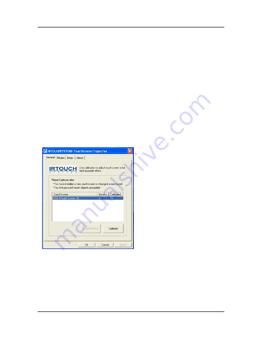
Touch Screen Calibration
1. Run “IrTouch Screen Control Panel” in the windows wallpaper of MagicInfo source.
2. Click “calibrate” button when the calibration window shows up.
3. Calibration is done by clicking on 4 calibration points so that user only clicks the center of the bull’s-eye in sequence.
4. If failing to hit the bull’s eye, user may move the pointer or fingers to the center of it again and lift based on the
utilization of Click on Release when calibration. Press” Esc” button to exit calibration.
5. After calibration the “recalibrate”, “OK”, “cancel” buttons will show up. “ReCalibrate” means recalibration; “OK” means
saving and exit; “Cancel” means exit without saving.
�
�
�
�
�
�
�
�
Summary of Contents for SyncMaster 320TSn-2
Page 11: ...3 8 3 Disassembly and Reassemble Memo...
Page 34: ...1 4 1 Precautions Memo...
Page 40: ...2 6 2 Product specifications Memo...
Page 43: ...4 3 4 Troubleshooting 4 2 1 Waveform...
Page 45: ...4 5 4 Troubleshooting 4 3 1 Waveform...
Page 47: ...4 7 4 Troubleshooting 4 4 1 Waveform...
Page 49: ...4 9 4 Troubleshooting 4 5 1 Waveform...
Page 51: ...4 11 4 Troubleshooting 4 6 1 Waveform...
Page 53: ...4 13 4 Troubleshooting 4 7 1 Screens to Check 16...
Page 65: ...6 1 6 Wiring Diagram 6 Wiring Diagram 6 1 Wiring Diagram Main...
Page 66: ...6 2 6 Wiring Diagram 6 2 Wiring Diagram Network...
Page 72: ...6 8 6 Wiring Diagram 6 8 Wiring Diagram...
Page 73: ...6 9 6 Wiring Diagram...


