


Front
LCD
panel
Figure
1.
Figure
2.
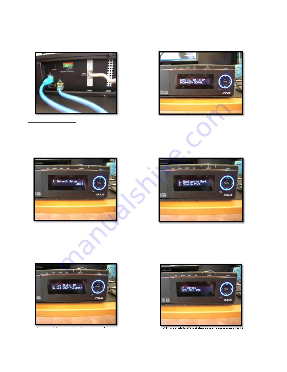
Basic
Configuration
Add
power
to
the
unit
using
the
Power
button
on
the
rear
panel
(
Figure
1
),
Use
the
down
arrow
on
the
front
panel
to
find
and
select
the
Network
Setup
menu(
Figure
3
)
then
click
ENTER.
Figure
3.
Figure
4.
Now
select
Option
1.
Monitoring
Port
(Figure
4)
then
click
ENTER
Now
select
Option
1.
Use
Static
IP
(Figure
5)
then
click
ENTER
Figure
5.
Figure
6.
Set
the
IP
address
and
Subnet
Mask
for
the
Monitor
port
(Figure
6),
use
this
IP
address
to
connect
via
Web
Server.


