


1-18
Samsung Electronics
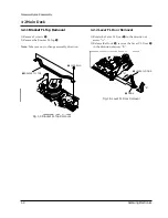
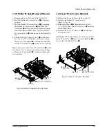
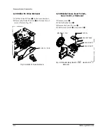
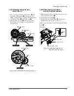
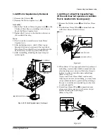
Disassembly and Reassembly
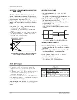
1-3 The table of clearing, Lubrication and replacement time about principal parts
1) The replacement time of parts is not life of parts.
2) The table 1-1 is that the VCR Set is in normal condition (normal temperature, normal humidity).
The checking period may be changed owing to the condition of use, runtime and environmental conditions.
3) Life of the Cylinder AssÕy is depend on the condition of use.
4) See exploded view for location of each parts.
<Table 1-1>
Æ : Cleaning O : Check and replacement in necessary
3
: Add Oil
T
A
P
E
P
A
T
H
S
Y
S
T
E
M
D
R
I
V
I
N
G
*
Parts Name
Checking Period
Remark
500
1000 1500 2000 2500 3000 3500 4000 4500 5000
POST TENSION
∆
∆
∆
∆
∆
∆
∆
∆
∆
∆
SLANT POST S, T
∆
∆
∆
∆
∆
∆
∆
∆
∆
∆
#8 GUIDE SHAFT
∆
∆
∆
∆
∆
∆
∆
∆
∆
∆
CAPSTAN SHAFT
∆
∆
∆
∆
∆
∆
∆
∆
∆
∆
#9 GUIDE POST
∆
∆
∆
∆
∆
∆
∆
∆
∆
∆
#3 GUIDE POST
∆
∆
∆
∆
∆
∆
∆
∆
∆
∆
GUIDE ROLLER S, T
∆
∆
∆
O
O
O
O
O
O
O
CYLINDER ASS’Y
∆
O
O
O
O
O
O
O
O
O
FE HEAD
∆
∆
∆
O
O
O
O
O
O
O
ACE HEAD
∆
O
O
O
O
O
O
O
O
O
PINCH ROLLER
∆
O
O
O
O
O
O
O
O
O
POST REEL S, T
3
3
3
3
3
SLEEVE TENSION
3
3
3
3
3
POST CENTER
3
3
3
3
3
LEVER IDLE BOSS (2Point)
3
3
3
3
3
CAPSTAN MOTOR PULLEY
∆
∆
∆
∆
∆
O
O
O
O
O
BELT PULLEY
O
O
O
O
O
O
O
HOLDER CLUTCH ASS’Y
∆
O
O
O
O
O
O
O
O
O
GEAR CENTER ASS’Y
O
O
O
O
O
O
O
O
O
GEAR IDLE (2Point)
O
O
O
O
O
O
O
O
O
LOADING MOTOR
O
O
O
O
O
O
O
O
O
BAND BRAKE ASS’Y
O
O
O
O
O
O
O
O
O
BRAKE T ASS’Y
O
O
O
O
O
O
O
O
O
S
Y
S
T
E
M
- Periodic time of applying oil
(Apply oil after cleaning)
- The excessive applying oil
may be the cause of malfunc-
tion.
- To clean the parts, use patch
and alcohol (solvent).
- After cleaning, use the video
tape after alcohol is gone
away completely.
- We recommend to use oil
[EP-56] or solvent.
- One or two drops of oil
should be applied after clean-
ing with alcohol.
B
R
A
K
E
S
Y
S
T
E
M
Summary of Contents for SVR-537
Page 17: ...Exploded View and Parts List 3 8 Samsung Electronics MEMO ...
Page 26: ...Schematic Diagrams Samsung Electronics 5 3 5 1 S M P S ...
Page 27: ...Schematic Diagrams 5 4 Samsung Electronics 5 2 Power Drive ...
Page 29: ...Schematic Diagrams 5 6 Samsung Electronics 5 4 Audio Video ...
Page 30: ...Schematic Diagrams Samsung Electronics 5 7 5 5 Hi Fi ...
Page 31: ...Schematic Diagrams 5 8 Samsung Electronics 5 6 RF VCP ...
Page 32: ...Schematic Diagrams Samsung Electronics 5 9 5 7 SECAM SVR 639 Only ...
Page 33: ...Schematic Diagrams 5 10 Samsung Electronics 5 8 Input Output 1 Scarrt Jack SVR 639 Only ...
Page 34: ...Schematic Diagrams Samsung Electronics 5 11 5 9 Input Output RCA Jack ...
Page 35: ...Schematic Diagrams 5 12 Samsung Electronics 5 10 OSD ...
Page 36: ...Schematic Diagrams Samsung Electronics 5 13 5 11 VFD Display SVR 639 ...
Page 37: ...Schematic Diagrams 5 14 Samsung Electronics 5 12 LED Module Display SVR 633 SVR 630 ...
Page 38: ...Schematic Diagrams Samsung Electronics 5 15 5 13 LED Single Display SVR 537 ...
Page 40: ...Schematic Diagrams Samsung Electronics 5 17 5 15 Remote Control Multi TV ...
Page 41: ...Schematic Diagrams 5 18 Samsung Electronics 5 16 Remote Control VCR Only ...
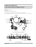
Page 66: ...2 6 Samsung Electronics Alignment and Adjustment MEMO ...


