background image

Digital Video Recorder        User’s Manual

68

Users can upgrade the software by doing a firmware download. You can download the firmware with 

a USB Memory stick.

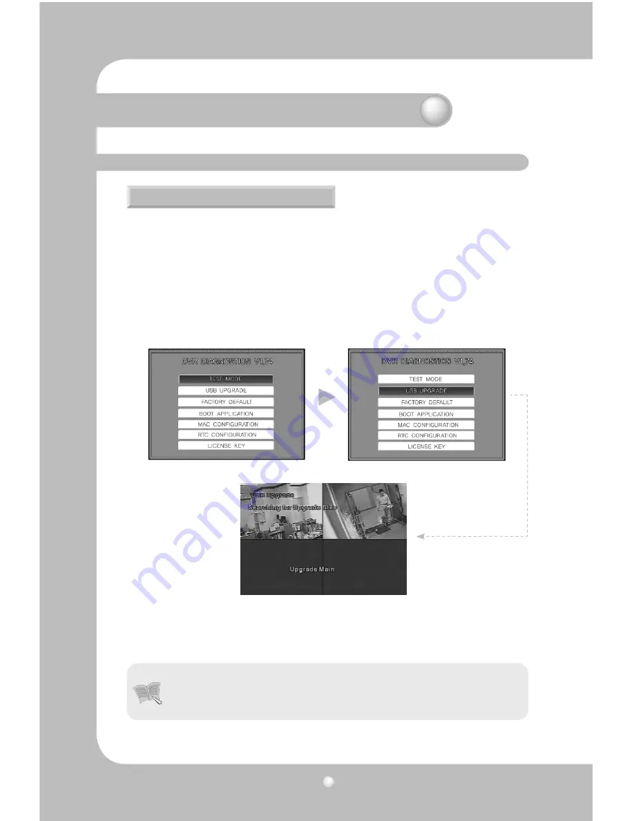
 Select 'MENU' and go to [SYSTEM SETUP]-[SYSTEM]-[TEST MODE].

 The DVR will reboot and the system will show the DVR DIAGNOSTICS MENU as below.

  Please create a folder in the USB memory stick and name it 'UPGRADE'. Copy the upgrade file into 

the folder and connect the USB memory stick to the DVR.  

The folder's name must be 'upgrade'. If the folder's name is not 'upgrade', the system cannot down

-

load the correct firmware from the USB memory stick.

 Select USB UPGRADE on the screen and the firmware upgrade automatically proceeds.

 When the upgrade is done, the DVR will be rebooted. Select BOOT APPLICATION in the test mode.

  The DVR will be rebooted again and go back to live monitoring screen mode. Now the firmware 

upgrade is completed.

5.14 ETC

5.14.1 Firmware Upgrade

•  The function to upgrade firmware over a network is not provided, because upgrading 

the firmware over a network could cause a fatal error in the system if th network got 

disconnected.

Chapter 5. Configuration

Notes

Summary of Contents for SVR-450

Page 1: ...Digital Video Recorder User s Manual 1 ...

Page 2: ...nts negligence alteration misuseorabuse Inaddition nowarrantyis offered for any attachments or parts not supplied by the manufacturer Thewarrantyperiodforthisproductwillbefor2yearsfromthedateofpurchase Thefollowingcases are not covered by the warranty and payment is required for repairs Malfunction due to negligence in handling by the user Deliberate disassembly and replacement by the user Connect...

Page 3: ...0 3 2 4 External connector 21 Chapter 4 Operating 25 4 1 Checklist before operation 25 4 2 Power connection 26 4 3 Live monitoring screen 26 4 3 1 Function of screen display 27 4 3 2 Automatic channel rotation 27 4 4 Recording 28 4 4 1 Normal recording 28 4 4 2 Scheduled recording 28 4 5 Search 29 4 5 1 Event search 29 4 5 2 Timeline search 29 4 5 3 Go To search 30 4 5 4 Go first search 30 4 5 5 G...

Page 4: ...5 7 3 Client access 53 5 7 4 RS 232 54 5 7 5 RS 422 485 54 5 7 6 E MAIL 54 5 8 DDNS Registration 55 5 8 1 DDNS Registration procedure 55 5 9 Instructions on using DDNS 59 5 10 Editing registered product 61 5 11 System setting 62 5 11 1 System 62 5 11 2 HDD 63 5 11 3 Password 64 5 11 4 User Authentication 64 5 11 5 CLOCK SETUP 65 5 12 PTZ 67 5 12 1 Setting for each channel 67 5 13 EXIT MENU 67 5 14...

Page 5: ...ventilator opening Donotapplyexcessiveforcewhenpullingonthepowercord Damagingthecordmaycauseanelectricshock or fire Random replacement of built in battery by other types of batteries may cause explosion The battery shall be replaced by the same battery The used batteries shall be disposed carefully because they can cause environment pollutions Dismantling and cleaning Donotdismantle repairormodify...

Page 6: ...sible for compliance could void the user s authority to operate the equipment NOTE ThisequipmenthasbeentestedandfoundtocomplywiththelimitsforaClassAdigitaldevice pursu anttopart15oftheFCCRules Theselimitsaredesignedtoprovidereasonableprotectionagainst harmfulinterferencewhentheequipmentisoperatedinacommercialenvironment Thisequipment generates uses andcanradiateradiofrequencyenergyand ifnotinstall...

Page 7: ...ntrol passwordsetting real time voice data storage and event lists and log file storage Monitoring Screen Recording TheSamsungSVR 940 SVR 450canrecordupto120framespersecond Italsorecordseventsonan event list as well as providing a pre event recording function Simultaneous execution of three functions recording playback and networking Convenient setting of recording frame by channel Up to 3 levels ...

Page 8: ... Model PLEOMAXR80X5210SJ TheSamsungSVR 940 SVR 450supportsawiderangeofnetworkssuchasLANandADSL DHCP The usercanalsoeasilyoperateandmanagethemainfunctionsoftheunitfromaremotelocationusingan exclusive PC viewer Liveimageviewfromaremotelocationavailable fullscreen quadscreen and9 channelscreenmode for SVR 940 selectable Search and playback by time or event from a remote location 10 100Mbps Ethernet x...

Page 9: ...upurchasetheunit pleasecheckthatthecomponentsspecifiedbelowareincluded Ifanycompo nents are missing please contact your local vendor SVR 450 940 Main unit 1 Network viewer program CD 2 User Manual 3 Remote controller 4 Batteries for remote controller 5 Adaptor For SVR 450 9 Power cable 2 2 1 Control panel on the front Chapter 2 Summary ...

Page 10: ... accessing HDD 6 Lights up when the system is recording video data Number Button Name Description 1 Press to power the system ON OFF 2 Press to navigate to and select a Menu item 3 Presstoselectandchangetheforwardorbackplayback Pressing thisbuttonduringforwardplaybackreversesthedirectionofplay 4 Forward Playback Speeds of 2X 4X 8X 5 PresstostopthePlaybackandtostartsearchingotherrecorded data 6 Pre...

Page 11: ... ÆON Ø 14 Presstoselectthelivedisplayformatasfullscreen quadscreen or 9 channel screen for SVR 940 display 15 Press to return to previous Menu screen 16 Press to move up in a Menu item in setup mode 17 Press to move right in a Menu item in setup mode 18 Press to move down in a Menu item in setup mode 19 Press to move left in a Menu item in setup mode 20 Presstoselectfullscreen quadscreen or9 chann...

Page 12: ... Output 4 VIDEO OUT Composite Video Output 5 VGA VGA output 6 RS 232 For the engineering console only not for other purposes 7 LAN RJ45 Connector 8 RS 485 422 PTZ camera control 9 SENSOR IN Sensor Input 10 ALARM OUT Alarm Output 11 SWITCHES NTSC PAL BNC VGA Select Switch Please refer to Chapter 5 for the detailed guide 12 SPOT Spot output For SVR 940 13 SVHS S VHS output Chapter 2 Summary ...

Page 13: ...AY PAUSE Button to Play and Pause the Playback screen FAST ButtonforForwardPlayback Speedsof2X 4X 8X DIR Buttontoselectandchangethedirectionofplayin playback Whenpressedduringforwardplayback the system reverses the direction of play ENTER Buttontoselectfullscreen quadscreen or9 channel screen for SVR 940 in live monitoring mode Itcanalsobeusedtoselectadesiredmenuitemor to store a setup value in th...

Page 14: ...r the full screen 8bit Brightness 256 Gray Scale 24bit Color 160 000 Colors Monitor Output 1 0Vp p Composite 75Ω 1 0Vp p Composite 75Ω S VHS VGA Output RGB Output Non Interlaced Scan Select composite or VGA Audio Items SVR 450 SVR 940 Audio 4CH Audio Input 1CH Audio Output Audio compression ADPCM Alarm Items SVR 450 SVR 940 Input 4 Channels 9 Channels Output 1 Relay output 4 Relay output Items SVR...

Page 15: ...Pre Event Recording Image Quality 3 Types of Recording Mode General Schedule Event Individual Channel ON OFF Setting 3 Stage Image Quality User Configurable Items SVR 450 SVR 940 Default HDD 1 ea Max 1ea 1 ea Max 2ea HDD type RPM Recommended EIDE 7200rpm Samsung Seagate Maxtor Please refer to the recommended HDD model list Password Items SVR 450 SVR 940 6 stage Password 4 digit Password including ...

Page 16: ...er recommended Monitor 1 024_768 Pixels LAN Interface 10 100 Base T RJ 45 Items SVR 450 SVR 940 Power DC 12V Adaptor SVR 450 100 127V 200 240V 50 60Hz Power Consumption Approx 25W 65W SearchandPlayback Items SVR 450 SVR 940 Search Mode Search by Time Year Month Date Hour Minute Search by Channel per channel Search by Event Alarm Motion Detect Search by the oldest data The first recording image Sea...

Page 17: ...for HDD plate Adaptor for SVR 450 Power cable Items SVR 450 SVR 940 Video Input BNC 4EA BNC 9EA Monitor Output BNC 1EA Loop out 9EA Spot 1EA S VHS VGA Output PC Monitor Audio Jack USB Port 9 Pin DSUB 6 Pin Terminal sector 8 Pin Terminal sector 2 Pin Terminal sector Termination Switch JP2 Termination LAN Input 15 Pin DSUB RCA Input 4 RCA Output 1 USB2 0 Firmware Upgrade Copy RS 232C Standby RS 422 ...

Page 18: ... Video Recorder User s Manual 18 SVR 450 SVR 940 3 1 How to connect all parts The connection layouts for the SVR 450 940 with the monitor CCTV and external devices are described as below Chapter 3 Installation ...

Page 19: ...upto4or9camerasrespectively ConnecttheBNCtermi nal of each camera to the CAMERA IN terminal of the unit TheSVR 450 950cansaveaudioinformation Forstorageoroutputofaudioinformation itisrequired to connect the relevant devices 3 2 1 Camera 3 2 2 Audio SVR 450 SVR 940 SVR 450 Chapter 3 Installation ...

Page 20: ...nmonitor ThereisalsoaVGAvideooutputforthePC monitor SVR 450 Audio input PleaseconnectanRCAaudiocabletotheAUDIOINconnector suchascamerawithbuilt inmicrophone and others All types of microphone and speaker are compatible with the system Chapter 3 Installation For Audio input setting set Audio to ON in the Recording setting menu Notes Whenplaybackwithaudioinsplitdisplaymodeisnotworkingproperly turnth...

Page 21: ...ion DuringplaybackwiththeVGAmonitor afewframescansometimesbemissingbut this is not a defect of the unit Sensor input SENSOR IN Asexternalsensorconnectingterminal signalsfromanexternalsensorordevicewillbeinputtothesystem Relay Output RELAY OUT ThisAlarmOutputterminalusesthecontactrelayforthealarmoutputtoexternaldevices Youcanselect NO Normal Open or NC Normal Close for connection according to the c...

Page 22: ...cation device on and off In the SWITCH section on the back of the SVR 940 there is a TERM switch SVR 450 Chapter 3 Installation 1 RS 422 Connecting Terminal Block s 4 Port orderly 2 RS 485 ShorttheTerminalBlock s1 3 Tx Rx Ports and2 4ports Tx Rx thenconnecting 1 2 ports or 3 4 ports to RS 485 TheoperationofeachrelayoutputcanbedefinedbyacombinationofMotionDetect andSensorintheEventSettingontheMainM...

Page 23: ...RS 485 1 TX Transmit Data 2 TX Transmit Data 3 RX Receive Data Data 4 RX Receive Data Data LAN Connection Ethernet 10 100 Base T This port is to connect to network SVR 450 Chapter 3 Installation 1 RS 422 Connecting Terminal Block s 4 Port orderly 2 RS 485 Connecting 3 4 ports to RS 485 ...

Page 24: ...he output connector for a VGA Monitor SVR 940 SVR 450 SVR 940 No Description No Description 1 TX Transmit Data 5 N C No connection 2 TX Transmit Data 6 RX Receive Data 3 RX Transmit Data 7 N C No connection 4 N C No connection 8 N C No connection Chapter 3 Installation ...

Page 25: ...YNC HorizontalSynchronization 6 Ground 14 VSYNC Vertical Synchronization 7 Ground 15 N C No connection 8 Ground 4 1 Checklist before operation Usersmustselectthevideomode NTSCorPAL andvideooutput BNCorVGA beforepoweringthe system on These can be selected from the switches on the rear of the DVR system The settings of the video mode and video output are as described below SETTING Video mode Video o...

Page 26: ...lt O X X O X O X O 4 2 Power connection 4 3 Live monitoring screen Afterpowerisconnectedtotherearconnectorofthesystem thesystemwillbepoweredon When power is turned on the system will detect a video signal automatically Despite of a power failure all the setting values will preserve When the system is turned ON the live monitoring screen is displayed Chapter 4 Operating ...

Page 27: ...llscreenmode eachchannelisrotatedautomatically following the setting in SCREEN SETUP Auto Sequence SEQUENCE must be set to YES When AUTO is pressed again the Auto sequence operation will be canceled Press the ENTER button and the four connected channels are displayed in quad split screen 4 3 1 Function of screen display 4 3 2 Automatic channel rotation Chapter 4 Operating ...

Page 28: ...rdingsetting isactivated Whilerecordingwiththepre recordingsetting theiconsbelowindicatethetriggerfor recording C CONTINUOUS RECORDING S SENSOR RECORDING M MOTION DETECTION RECORDING T TEXT RECORDING POS TEXT RECORDING NO VIDEO INPUT 0 NO RECORDING S SENSOR RECORDING NO RECORDING C CONTINUOUS RECORDING M MOTION DETECTION RECORDING T TEXT RECORDING Chapter 4 Operating Therecordingstatusiconsarechan...

Page 29: ...sor recording Text recording Manual recording etc When Event Search is selected the screen below is displayed Users can easily select a desired search time using the Time line bar PresstheENTERbuttonontheTimelinebartodisplaythecalendarandpresstheENTERbuttonagain to display as below Dates with any recorded data are displayed in a dark color Whenthedate channel andeventtypeareselectedandthePLAYbutto...

Page 30: ...rdedfileformat amaximumof1minuteofthelastrecorded can be played back Users can enter a desired search date and time and press the PLAY button to playback The second setting can be input as 15 seconds 30 seconds 45 seconds V1 V4 Time zones with recorded data are displayed with a colored bar SVR 940 V1 V9 A1 A4 Time zones with recorded audio data are also displayed with a colored bar Time zones with...

Page 31: ...otheHDDandselectthebackupdevice eitherUSBmemorystickor CD RW The still image will be transferred to the selected backup device PresstheSEARCHbuttonandselectARCHIVEtodisplaythecalendar Selectadesireddateandpress the ENTER button to display Figure 2 Selectadesiredlisttobebackedupandtheimageisdisplayed Selectthebackupdevice eitherUSB memory stick or CD RW When backup is completed Figure 3 is displaye...

Page 32: ... eitherUSBmemorystickorCD RW Selectthedevicethatyouwanttosave ittoanditwillbesavedtothatdevice PresstheSEARCHbuttonandselectARCHIVEtodisplaythecalendar SelectadesireddateandpresstheENTER buttontodisplayFigure2 Selectadesiredlisttobebackedupandtheimageisdisplayed Selectthebackupdevice eitherUSBmemorystick orCD RW Whenbackupiscompleted Figure3isdisplayed 4 5 7 2 Video backup Only available during Pl...

Page 33: ... forward DIR Button to select and change the direction of play in playback PressthePTZbuttonontheselectedFullLiveScreen andadjustthePan Tilt orZoomofacamera ThePTZfunction canbecontrolledbythefunctionbuttonsofthefrontpanelorbytheremotecontroller ThePTZfunctioncanbe controlledwhenaPTZcameraiscorrectlyconnectedtotheRS 485 Chapter 4 Operating Duringplayback afewframesmaybemissingdependingontheimagequ...

Page 34: ...on Select INITIALIZE and press the ENTER button to initialize a PTZ camera Select ZOOM FOCUS and press the ENTER button For Zoom adjustment Press the button For Focus adjustment Press the button 4 7 1 PAN TILT 4 7 3 INITIALIZE 4 7 2 ZOOM FOCUS Press the PTZ control button to move and press the button again to stop The PTZ Mode is available in the Live Screen Notes Chapter 4 Operating ...

Page 35: ...Dthatisprovidedinthepackage should be installed and run before the playback of the DVR format backup file 1 AfteryoubackupthevideodataasDVRtype there are3filesontheUSBmemoryfolder Figure1 FFDSHOW Setup Procedure Double click the ffdshow exe file icon in provided CD Choosethelanguageofprogram afterthatclickthe NEXT button continuosly no option change 2 ClickDVR Exclusive Playericon and thenyoucanse...

Page 36: ...edia File ClickthisicontoopenthemediafilesavedasDVRtype 2 Stop Click this icon to stop the playback 3 Rewind Click this icon to move reward for 5 seconds 4 Previous Frame Click this icon to move to the previous frame 5 Play ClickthisicontoplaythevideodatasavedasDVRtype 6 Pause Click this icon to pause the display screen 7 Next Frame Click this icon to move to the next frame 8 Forward Click this ic...

Page 37: ...SIZE REPEAT RECORD WARNING MESSAGE WARNING BEEP DETAILSETUP CHANNEL MODE SCHEDULE IMAGE FRAMERATE PRE EVENT DURATION POST EVENT DURATION AUDIO SENSOR SELECT The menu is configured as illustrated below SCREENSETUP SCREEN CHANNEL TITLE COVERT BRIGHTNESS CONTRAST SPOT TITLE DISPLAY SPOT MODE Only for SVR 940 AUTOSEQUENCE SEQUENCE SEQUENCE DWELL VIDEO LOSS SKIP STATUS OSD CLOCK DISPLAY HDD FREE SPACE ...

Page 38: ...WORK TYPE LAN DHCP ADSL IP ADDRESS SUBNET MASK GATEWAY DNS SWR DDNS SERVER DOMAIN ADDRESS ID PW RS 422 485 SYSTEM ID BAUD RATE DATA BIT PARITY BIT STOP BIT E MAIL E MAIL MAILADDRESS MAILSERVERIP RETURNMAILADDRESS PW CLIENT ACCESS PORT CLIENT ACCESS BANDWIDTH SAVING RS 232 SYSTEM ID BAUD RATE DATA BIT PARITY BIT STOP BIT SYSTEMSETUP SYSTEM LANGUAGE KEYBUZZER DEFAULT REMOTESETUP REMOTECON TROLLER ID...

Page 39: ...u Submenu Default SCREEN CHANNEL TITLE COVERT BRIGHTNESS CONTRAST CH1 4 950 CH1 9 CH1 OFF 50 50 AUTO SEQUENCE SEQUENCE SEQUENCE DWELL VIDEO LOSS SKIP OFF 1SEC OFF STATUS OSD CLOCK DISPLAY HDD FREE SPACE RECORD STATUS TITLE DISPLAY EVENT DISPLAY OSD CONTRAST ON ON ON ON ON ON 100 SPOT SVR 940 TITLE DISPLAY SPOT MODE ON Manual Main Menu Submenu Default GENERAL SETUP IMAGE SIZE REPEAT RECORD WARNING ...

Page 40: ...VICE CHECK PROTOCOL HEADER1 HEADER2 DELIMITER LINES CH1 NORMAL OFF 1 RELAY H1 CH2 CH3 CH4 SVR 450 CH1 CH2 CH3CH4 CH5 CH6 CH7 CH8 CH9 SVR 940 MD TEXT V LOSS HDD Error Main Menu Submenu Default NETWORK NETWORK TYPE IP ADDRESS SUBNET MASK GATEWAY DNS SWR DDNSSERVERDOMAINADDRESS ID PW LAN 172 16 1 52 255 255 0 0 0 0 0 0 172 16 1 220 OFF CLIENT ACCESS PORT CLIENT ACCESS BANDWIDTH SAVING 3495 ON OFF EVE...

Page 41: ...D USER AUTHENTICATION USER PASSWORD EVENT BEEP OFF CLOCK SETUP CLOCK DATE MODE MONTH TYPE YYYY MM DD INITIAL PTZ CHANNEL PTZ CAMERA ID MODEL CH1 0 NONE Main Menu Submenu Default RS 232 SYSTEM ID BAUD RATE DATA BIT PARITY BIT STOP BIT 0 9600 8 NONE 1 RS 422 485 SYSTEM ID BAUD RATE DATA BIT PARITY BIT STOP BIT 1 9600 8 NONE 1 E MAIL E MAIL MAIL ADDRESS MAIL SERVER IP ID PW RETURN MAIL ADDRESS OFF SY...

Page 42: ...are applied immediately SUB MENU MAIN MENU SETUP SETUP GUIDE Operation of the unit using the buttons on the main unit Move between Menus Press the Arrow buttons Change Setting Values Press the Buttons Exit from Menu Screen Press the ESC Button Operation using the Remote Control Move between Menus Press the Arrow buttons Change Setting Values Press the Buttons Exit from Menu Screen Press the ESC Bu...

Page 43: ...Down arrow button to move between character strings Toinsertspaces movethecursortoSPACEonthescreenandthenpressSELECTontheremote control or the ENTER button on the main unit COVERT Set whether to display or hide the selected channel WhenCOVERTissetto ON theselectedchannelisnotdisplayedonthescreenbutis recorded Thisfunctioncanbeusednottodisclosethechannelselectedtoanyoneelse 5 4 SCREEN SETUP Thisist...

Page 44: ... CH7 CH8 CH9 atthepredefinedswitching interval The channel switching interval can be set from 1 up to 10 on the SEQUENCE menu SEQUENCE Set it ON for Auto Sequence mode SEQUENCE DWELL Setthescreendisplaydurationbychannel Theswitchingintervalcanbesetfrom 1 up to 10 sec ORDER Select the channels for Auto Sequence USER DEFINE Select the display channels for Auto sequence in Quad mode display screen VI...

Page 45: ...s are displayed on the live screens EVENT DISPLAY ON OFF WithEventDisplay ON theeventinformationisdisplayedwhenanevent occurs OSD CONTRAST Set the contrast for Menu OSD The higher the the darker the OSD TITLE DISPLAY Select whether to display the channel name on the SPOT screen SPOT MODE Manual Select Manual and save this setting Press 0 onthesystemfrontbuttonor 10 ontheremotecontroller SP isdispl...

Page 46: ...NG MESSAGE WhentheremainingcapacityoftheHDDreachesapredefinedpercentage awarningmessageisdis played to users The warning level can be set from 1 to 10 5 10 in general 4 HDD WARNING BEEP WhentheremainingcapacityoftheHDDreachesthepredefinedpercentage awarningbeepisacti vated 5 5 1 GENERAL SETUP 5 5 RECORD SETUP ThisisasetupmenurelatedtotheDVRsystem PresstheMENUbuttonandselecttheTabusing theLeft Righ...

Page 47: ...PREEVENTDURATION issetas ON Incaseofrecording V LOSS thedataisrecordedonaLogfile V LOSSdatacanbesearchedforfromtheSEARCHmenu accordingthetimewhentheV LOSSoccurredasrecordedintheLogfile Pleasereferto 4 5 6 Log file search 5 5 2 DETAIL SETUP CONTINUOUS Continuous recording mode for 24 hours a day SCHEDULE Reserved recording MOTION DETECT Recordingisactivatedwhenthesystemdetectsmotionfrominputvideo i...

Page 48: ...estobestored Ataresolutionof 720X480 thesystemrecordsatmax 30fps Ataresolutionof360X240 thesystemrecordsatmax 12fps PRE EVENT DURATION Thisisthepre eventrecordingsetup Itautomaticallyrecords5secondsof pre eventdataifyousetitto5secs Pre eventrecordingisnotactivatedifyou set it to OFF POST EVENT DURATION Recordingcontinuesforthepredefinedtimefollowingtheoccurrenceofan event The available setting val...

Page 49: ...ONE Select the area for motion detection to Full or Partial zone FULLZONE DetectsmotionbyanalyzingthechangesinFullimagesfromcameras PARTIAL ZONE Users can select the desired zone for motion detection MOTION SENSITIVITY Youcansetthesensitivitytochangesonascreenfrom1to9 Highervaluesmean more precise motion detection 5 6 2 MOTION DETECTION ThismenuistosetuprecordingofPOSdataovervideo Inordertomatchit...

Page 50: ...at indicate the beginning ofTEXT data Two Headers can be input Delimiter Input letters that indicate the end of TEXT data LINES Set the number of lines to display TEXT data SYNC CHANNEL Select the channel to display TEXT data from a POS device DEVICE NORMAL SelectNORMALwhenconnectinganormalinputdevicesuchasabarcodescanningdevice Finger 007 Select Finger007 when connecting a finger print scan devic...

Page 51: ...esstheRightbuttontodisplaythenextpageofTEXTdataand presstheLeftbuttontodisplaythefirstpageofTEXTdata Availableduringpause Kalatel Quick Easy Mart 3197 Airport Loop Drive Costa Mesa Ca 92626 Candy Bar 1 49 Soft Drink 64oz 2 49 Chips 0 99 TOTAL 7 99 POS scenario SENSOR CH1 CH2 CH3 CH4 Whenthesensoroftheselectedchannelisactivated thesystemrelaysout MD When motion of the selected channel is detected t...

Page 52: ...nters the DNS address that the relevant Internet service provider assigns to a user ID Enters a User ID registered with the relevant service provider PW Enters a User Password registered with the relevant service provider DDNS SERVER ON OFF WhentheDVRisconnectedtoadynamicIP theIPaddresschangesevery timeitattemptstoconnecttotheISP Inthiscase thereisnowayforauser toknowthechangedIPaddress IfaDVRthat...

Page 53: ...t the SVR 450 to a router all three ports need to be set Default setting port on DVR Control Connect PTZ Events and other control data Default setting port 1 VIDEO Default setting port 2 AUDIO For example Default setting port on DVR 3495 Setting port for VIDEO 3496 Setting port for AUDIO 3497 CLIENT ACCESS Set the Network access password BANDWIDTHSAVING SelectBandwidthSavingON andframeratetransmis...

Page 54: ...seofstillimagecapturingatanevent inputtheIPaddresstosendthiscapturedimageto The conditions of sending e mail Ifthesettingvalueis Motion ON ON theDVRwillsende mailwithJPEGfilewheneventoccurs Whensettingvalueis ON ifthesystemIPischangedbyusingdynamicIP theDVRwillsende mail include changed IP information SYSTEM ID Set the system ID BAUD RATE Set the data transfer speed per second DATA BIT Set the dat...

Page 55: ...VER IP Please keep the default value ID Input the registered ID of the MAIL SERVER PW Input the registered PW of the MAIL SERVER RETURN MAIL ADDRESS Inputthee mailaddresstoreturnanundeliveredmailtothemailaddressthat is set from MAIL ADDRESS 5 8 1 DDNS Registration Procedure 5 8 DDNS Registration 1 Sign up at iPOLiS website The website www samsungipolis com Chapter 5 Configuration ...

Page 56: ...Digital Video Recorder User s Manual 56 Agreement the general terms and conditions SIGN UP page check ID availability Chapter 5 Configuration ...

Page 57: ...User s Manual 57 2 The product registration is possible after sign up Sign in at iPOLiS website Product List If you didn t register products there are no list Chapter 5 Configuration Product Registration Check ID availability ...

Page 58: ...at DVR Press the MENU button then select Network on OSD Menu DDNS Select Yes DDNS SERVER DOMAIN NAME Enter the DDNS server address Default www samsungipolis com ID PW EntertheID Domain PasswordusingtheproductregistrationatiPOLiSwebsite The DDNS configuration at DVR is completed Chapter 5 Configuration ...

Page 59: ...oduct Edit Delete Edit Delete the selected product password is needed for checking 4 The connection status of selected product can be checked on product list Chapter 5 Configuration The product ID domain can not be changed at registered status WhentheproductneedstochangetheID firstofall deletethedesiredproduct and register product again Caution ...

Page 60: ...lected User will be transferred to the appropriate page when the security code is entered Product ID Domain cannot be edited so if deleted ID Domain must be re entered View Move to the login web page of selected product Chapter 5 Configuration under Product Information Ifyouwanttomultichannelslivemonitoring searching playbacksimultaneously werecommendtousingSNM 64S Ps wprogram TheiPOLiSwebsitedoes...

Page 61: ...ser s Manual 61 Chapter 5 Configuration Click the edit button from the product list i Editing product profile ii Deleting Product 5 10 Editing registered product Click delete from the product list Registered product is deleted ...

Page 62: ...ZZER Selects whether to generate a key sound when pressing the buttons DEFAULT Initializes the setting values of the unit to the factory default values REMOTE SETUP Selectswhetherthesystemsettingscanbechangedfromaremotesiteoverthenetwork REMOTE CONTROLLER ID SettheremotecontrolID AremotecontrollerIDcanbeselectedfrom numbers0to9 TheremotecontrollerIDisdisplayedwithaniconsuchas R 1 R 2etconthescreen...

Page 63: ...ase refer to Chapter 5 14 1 Firmware upgrade HDD FORMAT SelectwhethertoinitializetheHDD SelectONtodeletealldatasavedintheHDDand the unit will automatically reboot for system stabilization HDDDESCRIPTION Detailedinformationsuchasthesize andrecordingstarttimeoftheHDD 5 11 2 HDD Chapter 5 Configuration ...

Page 64: ...bleto control the given functions The password should consist of four numbers e g 1 2 3 4 USER PASSWORD Set the user password Admin USER 1 3 A password is composed of digits from 1 to 9 EVENTBEEP Thesystemwillbeepoutwhenauserinputsthewrongpasswordmorethanthreetimes 5 11 3 Password 5 11 4 User Authentication Select whether to pop up window that asks for a Password When it selects to pop up a Passwo...

Page 65: ... page Only an administrator can view this page Inthecaseof PASSWORDCHECK X thesystemdoesnotarchiveanydataaboutwhologsinto the system menu Everybody can view SYSTEM SETUP PASSWORD USER AUTHORIZATION When the user is the only one who operates the system this setting can be available Onlywhenthe PASSWORDCHECK issetto O canadiscriminatoryauthoritybesetforeachof the functions MENU Set the authority to ...

Page 66: ...IME SERVER Input the address of the NTP TIME SERVER GMT GreenwichMeanTime GMT isatermoriginallyreferringtomeansolartimeatthe RoyalObservatory GreenwichinLondon BecauseNTPsynchronizesclockswith GreenwichMeanTime GMT regardlessofgeography usersmustsettheirowntime difference Ex KOREA GMT 09 00 DATE MODE Set the date format There are three type of date format YEAR MONTH DATE YEAR MONTH DATE MONTH DATE...

Page 67: ...SCP COSTAR2500 KALATELKTD 312 SENSORMATIC PTZ ELMOPTC 200 WOOJU DRX 502A KCC PT400 VIDOB 01 LGLPT A100L TSC PIH 302 DS 120 SCC 641 WV CS850 VC C50I NIKO NK 97 NEWBORN DOME SJ 100 DY 255 HRX 700 ERNA VICON VPS1300 V2311RB3 422R CNB PTZ102N SONY EVI D30 ThisisasetupmenurelatedtotheDVRsystem PresstheMENUbuttonandselecttheTabusing theLeft Rightbutton Thesubmenurelatedtothesystemappearsasillustratedbel...

Page 68: ... Thefolder snamemustbe upgrade Ifthefolder snameisnot upgrade thesystemcannotdown load the correct firmware from the USB memory stick Select USB UPGRADE on the screen and the firmware upgrade automatically proceeds Whentheupgradeisdone theDVRwillberebooted SelectBOOTAPPLICATIONinthetestmode TheDVRwillberebootedagainandgobacktolivemonitoringscreenmode Nowthefirmware upgrade is completed 5 14 ETC 5 ...

Page 69: ...TCH error message Whentheabovemessageisdisplayed powerthesystemOFF PleasethepowerthesystemON pressingtheESCbutton PresstheESCbuttonandholdituntiltheinitialmessageisdisplayedon thescreenasbelow ThenthesystemwillaskwhethertoenterintotheDVRDIAGNOSTICSMENU Iftheuserselects YES theDVRDIAGNOSTICSMENUwillbestarted Whenthepasswordispre set the password window is displayed Select RTC Configuration The pict...

Page 70: ...data will be deleted The DVR will be rebooted Select BOOT APPLICATION Items Description MODEL Select the system to connect with using to Web viewer Select from 440 450 940 6 1 Login page Chapter 5 Configuration Please check if the USB memory stick is compatible with the DVR SAN DISK CO PRETEC LG INNOTECH C C TRANSCEND etc TESTMODE FACTORYDEFAULT MACCONFIGURATION isformanufacturer suse only Please ...

Page 71: ...ConnectionType is IPAddress Whenthe ConnectionType is iPolisServer thedefaultsettingvalueis displayed The default setting value is www samsungipolis com Port Inputtheportnumberofthesystemifthe ConnectionType is IPAddress InputthesystemIDthatwaspre registeredintheiPOLiShomepage when the Connection Type is iPolis Server USER ID OnlytheUSERIDthatispre setin SYSTEMMENU PASSWORD USERAU THORIZATION ofth...

Page 72: ... 940 450 models Button to control audio Works when the user logs in as Admin Button to change the PAN TILT mode of speed dome cameras Before using this function please set the PTZ field to 0 in SYSTEM MENU PASSWORD USER AUTHORIZATION ButtontochangetheZOOM FOCUSmodeofspeeddomecameras Before using this function please set the PTZ field to 0 in SYSTEM MENU PASSWORD USER AUTHORIZATION Button for ZOOM ...

Page 73: ...tons to start and stop play Buttons to move 1 frame back 1 frame forward Buttons to fast rewind fast forward play 2 x and 4x play speeds Windowtodisplaythecalendar Dateswithrecordeddataaredisplayed incolors Whenadateisclicked thewindowbelowshowstimebarswith the data Select the time to play the data 6 3 SEARCH mode Chapter 6 Web Viewer ...

Page 74: ...ed channel 4 9 16 channels Button for Search Mode Display camera OSD menu ZF mdoe Buttonstoselectthespeeds for Pan Tilt Zoom Focus Max 6X Close camera OSD menu Button to go or return to the selected menu in the camera OSD menu Buttons for Zoom Focus of camera OSD control ZOOM IN FOCUS IN ZOOM OUT FOCUS OUT Chapter 6 Web Viewer ...

Page 75: ...Digital Video Recorder User s Manual 75 2 Search Mode lected the selected menu Button for Live Mode Calendar Play buttons Button for OSD control over video screen Show hide Chapter 6 Web Viewer ...

Page 76: ...ting it directly toward the unit s receiver If the unit ID and the remote control ID do not match set the same ID for both devices HDD recording is not performed TheHDDwillnotrecordvideoiftheservicelifeoftheHDDhascometoanendortherearebad sectors in the HDD In these cases replace the HDD The unit does not perform Scheduled Recording CheckwhethertheScheduledRecordingStart Endtimesandthecurrenttimear...

Page 77: ...52X240 Mode Normal Schedule Event TEXT HDD 160GB 1EA 250GB 1EA Max 2EA Backup Copy USB Memory Stick CD RW Serial Interface RS 485 422 Alarm Input Output 4IN 1OUT 9IN 4OUT Audio Input Output 4IN 1OUT NETWORK Interface RJ 45 10 100 Base t Protocol TCP IP DHCP PPPoE Software SNM 64S P Remote Control To control up to 9 DVRs OSD GUI Multi Language Support Temperature Operation 5 40 Storage 10 60 Power ...

Page 78: ...4 HDDVIBRATION ISOLATORS 5 SCREW 6 SATA HDD JUMPER COMPANY MODEL SIZE RPM BUFFER Reconi tion Record Playback Seagate ST31000340SV Surveillance 1TB 7200RPM 16MB OK OK OK ST3500830SCE 500GB 7200RPM 8MB OK OK OK ST3250410AS Barracuda 250GB 7200RPM 16MB OK OK OK ST3250310SV Surveillance 250GB 7200RPM 8MB OK OK OK ST3160815AS Barracuda 160GB 7200RPM 8MB OK OK OK HITACHI HDS721010KLA330 1TB 7200RPM 32MB...

Page 79: ...board screw on the only upper right corner like the picture below 3 Select Master or Slave using the Jumper switch on SATA converter board Set the Master Slave using the Jumper switch Set the Master Slave using Jumper switch JUMPER Switch In case of installing two HDDs firstly set the Master Slave If One HDD is Master the other should be set to Slave Need assy Screw ...

Page 80: ...t to the power SMPS using power cable 1st HDD the main power cable 2nd HDD the sub power cable When you use two HDDs HDDs should be same model and have same interface Connect with E IDE HDD cable and power cable a Direction of the SATA Converter board b Direction of the main power Sub power cable for SATA Converter board Connect to the power cable Connect to the E IDE HDD cable ...

Page 81: ...K HDS722525V LAT80 250 GB 7200 RPM 8 M OK OK OK HDT722525D LAT80 250 GB 7200 RPM 8 M OK OK OK HDT725025V LAT80 250 GB 7200 RPM 8 M OK OK OK HDT725032V LAT80 320 GB 7200 RPM 8 M OK OK OK HD S725050KLAT80 500 GB 7200 RPM 8 M OK OK OK MAXTOR 6L300R0 300 GB 7200 RPM 16 M OK OK OK SAMSUNG SP0822N 80 GB 7200 RPM 2 M OK OK OK SP1604N 160 GB 7200 RPM 2 M OK OK OK Western Digital WD1600BB 22 GUA0 160 GB 72...

Page 82: ... 120 GB 7200 RPM 2 M OK OK OK ST31600 22ACE 160 GB 7200 RPM 2 M OK OK OK ST3300820ACE 300 GB 7200 RPM 8 M OK OK OK ST3300831ACE 300 GB 7200 RPM 8 M OK OK OK ST3400832ACE 400 GB 7200 RPM 8 M OK OK OK ST3400820ACE 400 GB 7200 RPM 8 M OK OK OK ST3500641A 500 GB 7200 RPM 16 M OK OK OK ST3750840ACE 750 GB 7200 RPM 8 M OK OK OK ST3750640A 750 GB 7200 RPM 16 M OK OK OK ...

Page 83: ...MEMO ...

Page 84: ...MEMO ...

Page 85: ...MEMO ...

Page 86: ... 462 120 Korea TEL 82 31 740 8151 8158 FAX 82 31 740 8145 SAMSUNG OPTO ELECTRONICS UK LTD Samsung House 1000 Hillswood Drive Hillswood Business Park Chertsey Surrey KT16 OPS TEL 44 1932 45 5308 FAX 44 1932 45 5325 www samsungtechwin com www samsungcctv com SALES NETWORK VAN 08 11 ...

Reviews: