


Samsung Electronics
2-1
2. Alignment and Adjustment
2-1 Reference
1) X-Point (Tracking center) adjustment, “Head switching adjustment” and “NVRAM option setting” can be adjusted with remote control.
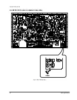
2) When replacing the Micom (IC601) and NVRAM (IC605 ; EEPROM) be sure to adjust the “Head switching adjustment” and
“NVRAM option setting”.
3) When replacing the cylinder ass’y, be sure to adjust the “X-Point” and “Head switching adjustment”.
4) Among Samsung VCR remote control used for adjustment as a accessory, only the remote control that has figures buttons (0 ~ 9) is
available for all adjustment regardless of chassis.
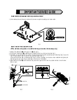
5) How to adjustment.
- Press the “SW718 (TEST)” button on Main PCB to set the adjustment mode.
- If the corresponding adjustment button is pressed, the adjustment is performed automatically.
- If the adjustment is completed, be sure to turn the power off.
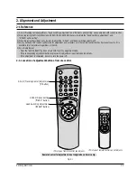
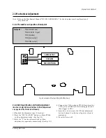
2-1-1 Location of adjustment button of remote control
Fig. 2-1
Q-PRO
IPC
DISPLAY
SHUTTLE
V-LOCK
CLR/RST F.ADV
INPUT INDEX
TRK PROG
RE
C
MENU
AU
DIO
SP
EE
D
TV/VCR
REPEAT
OK
<This type of remote control can adjust.>
<This type of remote control can not adjust.>
Remote Control for adjustment is not supplied as a Service Jig.
REPEAT
STANDBY/ON DISPLAY
CNT.RESET SPEED
IIP/S IPC
TRK
REC MENU
Head Switching Adjustment
("SPEED" Button)
NVRAM Option Setting
("MENU" Button)
X-Point (Tracking Center) Adjustment
("5" Button)
STANDBY/ON EJECT
Summary of Contents for SVR-433
Page 10: ...2 6 Samsung Electronics Alignment and Adjustment MEMO ...
Page 18: ...Exploded View and Parts List 3 8 Samsung Electronics MEMO ...
Page 24: ...4 6 Samsung Electronics Electrical Parts List MEMO ...
Page 27: ...Schematic Diagrams Samsung Electronics 5 3 5 1 S M P S Free Voltage SVR 433 233 230B 230W 131 ...
Page 28: ...Schematic Diagrams 5 4 Samsung Electronics 5 2 S M P S 230 Voltage SVR 2301 ...
Page 29: ...Schematic Diagrams Samsung Electronics 5 5 5 3 Power Drive ...
Page 31: ...Schematic Diagrams Samsung Electronics 5 7 O S D 5 5 Audio Video OSD ...
Page 32: ...Schematic Diagrams 5 8 Samsung Electronics 5 6 TM Block Input Ouput ...
Page 33: ...Schematic Diagrams Samsung Electronics 5 9 5 7 Remote Control Multi TV ...
Page 34: ...Schematic Diagrams 5 10 Samsung Electronics 5 8 Remote Control VCR Only ...


