Samsung SV-C90P Owner'S Manual Download Page 3

Safety Instructions

iii

9.  Cart Usage-A product and cart combination should be moved with care. Quick stops, excessive force, and uneven 

surfaces may cause the product and cart combination to overturn.

10.  Ventilation-Slots and openings in the cabinet are provided for ventilation and to ensure reliable operation of the 

product and to protect it from overheating. these openings must not be blocked or covered. The openings should 
never be blocked by placing the product on a bed, sofa, rug, or other similar surface. This product should not be 
placed in a built-in installation such as a bookcase or rack unless proper ventilation is provided or the manufacturer’s 
instructions have been adhered to.

11.  Power Sources-This product should be operated only from the type of power source indicated on the marking label. 

If you are not sure of the type of power supplied to your home, consult your product dealer or local power company. 
For products intended to operate from battery power, or other sources, refer to the operating instructions.

12.  Grounding or Polarization-This product may be equipped with a polarized alternating-current line plug (a plug 

having one blade wider than the other). This plug will fit into the power outlet only one way. This is a safety feature. 
If you are unable to insert the plug fully into the outlet, try reversing the plug. If the plug should still fail to fit, contact 
your electrician to replace your obsolete outlet. Do not defeat the safety purpose of the polarized plug.

13.  Power-Cord Protection-Power-supply cords should be routed so that they are not likely to be walked on or pinched 

by items placed upon or against them, paying particular attention to cords at plugs, convenience receptacles, and the
point where they exit from the product.

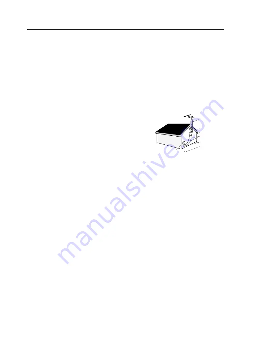
14.  Outdoor Antenna Grounding-If an outside antenna or cable system is

connected to the product,be sure the antenna or cable system is 
grounded so as to provide some protection against voltage surges and 
built-up static charges. Section 810 of the National Electrical Code, 
ANSI/NFPA 70 provides information with regard to proper grounding of 
the mast and supporting structure, grounding of the lead-in wire to an 
antenna discharge unit, size of grounding conductors, location of antenna-
discharge unit, connection to grounding electrodes, and requirements 
for the grounding electrode.

15.  Lightning-For added protection for this product during a lightning storm

or when it is left unattended and unused for long periods of time, unplug it from the wall outlet and disconnect the 
antenna or cable system. This will prevent damage to the product due to lightning and power-line surges.

16.  Power Lines-An outside antenna system should not be located in the vicinity of overhead power lines or 

other electric light or power circuits, or where it can fall into such power lines or circuits. When installing an outside 
antenna system, extreme care should be taken to keep from touching such power lines or circuits as contact with 
them might be fatal.

17.  Overloading-Do not overload wall outlets, extension cords, or integral convenience receptacles as this can result in 

a risk of fire or electric shock.

18.  Object and Liquid Entry-Never push objects of any kind into this product through openings as they may touch 

dangerous voltage points or short-out parts that could result in a fire or electric shock. Never spill liquid of any kind on
the product.

19   Servicing-Do not attempt to service this product yourself as opening or removing covers may expose you to 

dangerous voltage or other hazards. Refer all servicing to qualified service personnel.

20   Damage Requiring Service-Unplug this product from the wall outlet and refer servicing to qualified service 

personnel under the following conditions:
a

When the power-supply cord or plug is damaged.

b

If liquid has been spilled or objects have fallen into the product. 

c

If the product has been exposed to rain or water.

d

If the product does not operate normally by following the operating instructions. Adjust only those controls 
that are covered by the operating instructions as an improper adjustment of other controls may result in damage
and will often require extensive work by a qualified technician to restore the product to its normal operation.

e

If the product has been dropped or damaged in any way.

f

When the product exhibits a distinct change in performance-this indicates a need for service.

21.  Replacement Parts-When replacement parts are required, be sure the service technician has used replacement 

parts specified by the manufacturer or that have the same characteristics as the original part. 
Unauthorized substitutions may result in fire, electric shock, or other hazards.

22.  Safety check-Upon completion of any service or repairs to this product, ask the service technician to perform safety 

checks to determine that the product is in proper operating condition.

23.  Heat-The product should be situated away from heat sources such as radiators, heat registers, stoves, or other 

products (including amplifiers) that produce heat.

Antenna Lead-in Wire

Ground Clamp
Antenna Discharge Unit
(NEC Section 810-20)
Grounding Conductors
(NEC Section 810-21)

Power Service Grounding
Electrode System
(NEC Section 810-21)

Grounding Clamps

Electric Service Equipment

NEC-NATIONAL ELECTRICAL CODE

Summary of Contents for SV-C90P

Page 1: ...Video Cassette Recorder Owner s Manual Hi Fi SV C90P ...

Page 2: ...ous to make any kind of contact with any inside part of this product This symbol alerts you that important literature concerning operation and maintenance has been included with this product As an ENERGY STAR Partner Samsung Electronics America Inc has determined that this product or product model meets the ENERGY STAR guidelines for energy efficiency Important Safety Instructions 1 Read Instructi...

Page 3: ...a or cable system This will prevent damage to the product due to lightning and power line surges 16 Power Lines An outside antenna system should not be located in the vicinity of overhead power lines or other electric light or power circuits or where it can fall into such power lines or circuits When installing an outside antenna system extreme care should be taken to keep from touching such power...

Page 4: ... Selecting the On Screen Language 7 Setting the Clock 8 Setting the Channels 9 VCR Functions 11 VCR Operation Playing a cassette 12 Instant play 12 Tape Controls 13 Using the DISPLAY Button 15 Tracking 16 About Video Cassette Tapes 16 Recording 17 One Touch Recording OTR 17 Timer Recording 18 Choosing Audio 19 Care and Maintenance 20 Troubleshooting 21 Guide de reference rapide 22 Specifications 2...

Page 5: ...h Digital Auto Tracking Special effects playback including slow motion Built in HQ High Quality video circuitry One month eight event timer programming Check to make sure the following items have been included with your VCR 1 5V 1 5V ELECTRONICS Remote Control Batteries for remote 2AA RF Cable Warranty Card Features Accessories Owner s Manual Owner s Manual ...

Page 6: ... VCR on and off 2 EJECT Press to eject a tape or press 3 CASSETTE COMPARTMENT Insert a video cassette 4 REW REWIND Press to rewind in stop mode or reverse search in play mode 5 F F FAST FORWARD Press to fast forward in stop mode or forward search in play mode 6 PLAY Press to play tape 7 STOP Press to stop tape SV C90P Front Panel and Display 1 2 3 4 6 5 7 ...

Page 7: ...ment 3 Replace the compartment cover POWER Press to turn your VCR on and off TV VCR Switch between TV or VCR source See page 4 CH Press to change channels TRK Press to adjust cassette tracking DISPLAY Press for on screen information displays REC Press to start VCR recording STOP PLAY P S REW FF Press to control cassette playback or to move a cursor in the on screen menu CLEAR Press to set counter ...

Page 8: ... use an adapter to connect the antenna to the VCR input termi nal You can purchase an adapter at an electronics store If your antenna already has a round lead simply connect it to the terminal on the rear panel of the VCR Once your antenna is connected to the VCR connect a cable from the VCR to your TV from the Out to TV terminal on the rear panel of the VCR Cable Connections Basic Cable TV Connec...

Page 9: ...ching another scrambled or unscrambled You will need to Set TV channel to the output channel of the cable box Turn on the cable box and select cable channel 3 or 4 according to the output channel of the VCR To record a channel while watching another press TV VCR on the remote control to set the VCR to TV mode and select a desired cable channel on the cable box Premium Cable TV Connection 1 This se...

Page 10: ...R Setup External Stereo Connections Out to Audio System Connecting your stereo VCR to an external amplifier and speakers can improve the sound quality The sound from the VCR can be heard through the stereo ...

Page 11: ...nel as the CH3 4 switch on the rear panel of the VCR Press the TV VCR button on the remote control to set VCR mode Note The on screen menu differs from model to model 1 To select the language for the on screen menu display press the MENU button on the remote control 2 Press on the remote control to select Language 3 Press to select the language you want for the on screen menus English Spanish Fren...

Page 12: ...to the next setting 4 To enter the current year press or The day of the week is automatically added after you set the year 5 Press the MENU button to start the clock Press the MENU button again when you finish setting the clock Setting the Clock MAIN MENU Timer recording Clock set adjust Channel setup VCR function setup Language Lengua Langue MENU EXIT CLOCK SET ADJUST TIME DATE YEAR 9 00 5 05 199...

Page 13: ...on Press and to select CHANNEL SETUP 2 Press and to start Auto channel memory function 3 Your VCR will begin scanning through available chan nels To interrupt press the MENU button on the remote control When the channel number on screen stops changing the VCR has finished MAIN MENU Timer recording Clock set adjust Channel setup VCR function setup Language Lengua Langue MENU EXIT MAIN MENU Timer re...

Page 14: ...e To add a channel use CH For example To delete a channel use 4 To ADD the selected channel Press button on the remote control To DELETE the selected channel Press à button on the remote control When you have finished press the MENU button twice MAIN MENU Timer recording Clock set adjust Channel setup VCR function setup Language Lengua Langue MENU EXIT CHANNEL SETUP Ant Cable CABLE TV Auto channel...

Page 15: ...Access the VCR FUNCTION SETUP menu as described Press to set the cursor to Auto play then press to set ON or OFF When Auto play is ON the VCR will automatically begin playing a video tape when it is inserted as long as the safety tab of the cassette has been removed see page 16 Press the MENU button on the remote control when you are finished MAIN MENU Timer recording Clock set adjust Channel setu...

Page 16: ...t off 1 or 2 hours after the last button is pressed VCR FUNCTION SETUP Record speed SP Audio output MONO Tape length T120 Auto play ON Auto repeat OFF Auto power off 1Hr MENU EXIT VCR FUNCTION SETUP Record speed SP Audio output MONO Tape length T120 Auto play ON Auto repeat ON Auto power off OFF MENU EXIT Playing a cassette Instant play 1 Load a recorded cassette Power is automatically turned on 2...

Page 17: ...ce while a tape is playing for forward search Press PLAY to stop search Press and hold to increase speed by 7 times for tapes recorded at SP speed and 21 times for tapes recorded at SLP speed Release button to play Rewind and Reverse Search Press Rewind when the tape is stopped to rewind the cassette at top speed Press the Rewind button once while a tape is playing for rewind search Press PLAY to ...

Page 18: ...s for about five seconds 4 Press PLAY to view that program If you don t press PLAY the VCR automatically searches for the next index or until the end of tape is reached 2 Go to 0 00 00 stop Use this feature when you want to search for the 0 00 00 counter position on a cassette Press CLEAR at the point on the tape where you want to set the counter to 0 00 00 Later while a cassette is playing or sto...

Page 19: ...ng the DISPLAY screen 1 Press the DISPLAY button while the cassette is playing or recording After approximately 3 seconds the display automatically changes then only the counter and graphic displays are shown 2 Press the DISPLAY button to switch the counter mode between showing the time remaining on the tape and the present time of day 3 Press the DISPLAY button again to remove display from the TV...

Page 20: ... amount of jitter or some streaks are normal during still viewing Note The noise on the screen may not be completely eliminated depending on the tape used especially when the tape was recorded on another VCR Tape speeds The VCR can record at two tape speeds The slower speed SLP allows the VCR to record more program material on a tape Tapes recorded at standard speed SP provide a clearer picture Se...

Page 21: ...ss the TV VCR button on the remote control to select TV viewing Select the channel you want to watch with the TV s channel buttons Recording One Touch Recording OTR 1 Insert a video tape check the tape speed and select the channel you want to record using the CH 2 Press the REC button on the remote control the number of times that corresponds to length of record time you desire see chart below The...

Page 22: ...ime you have set To stop a Timer Recording press the VCR power button Note When using a cable decoder box or DSS make sure the decoder box is on and set to the correct channel for timer recording CH START END DATE SPD Ã MENU CLEAR Auto Speed Select If you are not sure the tape is long enough for timer program recording in the SP tape speed set the recording tape speed to AUTO Recording starts in t...

Page 23: ...thout noise To Record SAP Programs 2 To select SAP press the AUDIO button on the remote control until SAP is displayed on screen SAP will be displayed on the TV screen when a SAP broadcast is received Press the REC button for SAP recording When MAIN is displayed stereo is selected Selecting Playback Sound with Hi Fi Tapes 3 During playback press AUDIO to set the Audio to HI FI LEFT RIGHT or to MON...

Page 24: ... is not a common prob lem and unless it appears the heads should not be cleaned If necessary purchase a head cleaning cassette If the picture quality does not improve after cleaning call 1 800 SAMSUNG for service When cleaning the video heads read all the instructions provided with the head cleaning cassette Incorrect head cleaning can permanently damage the video heads Video Cassettes High qualit...

Page 25: ...te Make sure the VCR was in STOP or Power Off mode before recording Check if there was a power failure or broadcast scheduling change Check if the cassette recorded any picture Press TRK to adjust the playback picture Press TV VCR for VCR viewing Set the TV channel to match the VCR Output channel Make sure the TV is working properly Press TV VCR for TV viewing Check all cabling between VCR Antenna...

Page 26: ...para descifrar o decodificar los canales pagos y o los canales básicios Siga el diagrama para conectar el VCR auna caja decodificadora Coloque el interruptor de Canal de Salida ubicado en la parte posterior del VCR en 3 ó 4 para igualar el canal seleccionado en el televisor POWER Presione para encender y apagar el VCR CH Presione para cambiar canales TRK Presione para ajustar el seguimien to de la...

Page 27: ...os pocos segundos de seguimiento automático debería escucharse el sonido Para Realizar Ajuste de la Hora 1 Prenda el VCR y oprima MENU para obtener el Menú Principal Oprima y para seleccionar elAjuste de la hora 2 Oprima y para indicar la hora del día 3 Oprima y para indicar el mes la fecha y dos últimos números que correspondan al año 4 Oprima MENU para concluir Para Cambiar la selección de Idiom...

Page 28: ...0V AC AUTO 50 60Hz Power Output App 18 watts on App 3 8 watts off Dimensions 320mm W X 94mm H X 238mm D 12 6 W X 3 7 H X 11 D Weight 2 6kg 5 7lbs Your VCR can receive 68 broadcast TV channels or up to 125 unscrambled cable channels Check your local cable company for complete compatibility requirements Type Number Channel List of Channels On Air 12 VHF Channels 2 13 56 UHF Channels 14 69 CATV 113 C...

Page 29: ...98 12 11 Version 0 1 ...

Reviews: