Samsung STM-32L Instruction Manual Download Page 3

INSTRUCTION MANUAL

4

5

INSTRUCTION MANUAL

SAFETY INSTRUCTION   

CAUTIONS

ATTENTION

-  The apparatus shall not be exposed to dripping or splashing and that no objects filled with liquids, such as vases, 

shall be placed no the apparatus.

- Minimum distances(e.g. 10cm) around the apparatus for sufficient ventilation.

“WARNING - To reduce the risk of fire or electric shock, do not expose the apparatus to rain or moisture.”

“ The apparatus shall not be exposed to dripping or splashing and no objects filled with liquids, such as vases, shall 

be placed on the apparatus.”

The power supply cord is used as the main disconnect device, ensure that the socket-outlet is located/installed 
near the equipment and is easily accessible.

Le cordon d`alimentation est utillsé comme interrupteur général. La prise de courant doit être située ou installée à 
proximité du matériel et être facile d`accès

• NEVER REMOVE THE BACK COVER

Removal of the back cover should be carried out only by qualified personnel.

• DO NOT USE IN HOSTILE ENVIRONMENTS

To prevent shock or fire hazard, do not expose the unit to rain or moisture.
This unit is designed to be used in the office or home. Do not subject the unit to vibrations, dust of corrosive 
gases.

• KEEP IN A WELL VENTILATED PLACE

Ventilation holes are provided on the cabinet to prevent the temperature from rising.
Do not cover the unit or place anything on the top of unit.

• AVOID HEAT

Avoid placing the unit in direct sunshine or near a heating appliance.

• TO ELIMINATE EYE FATIGUE

Do not use the unit against a bright back ground and where sunlight or other light sources will shine directly on 
the monitor.

• BE CAREFUL OF HEAVY OBJECT

Neither the monitor itself nor any other heavy object should rest on the power cord.
Damage to a power cord can cause fire or electrical shock.

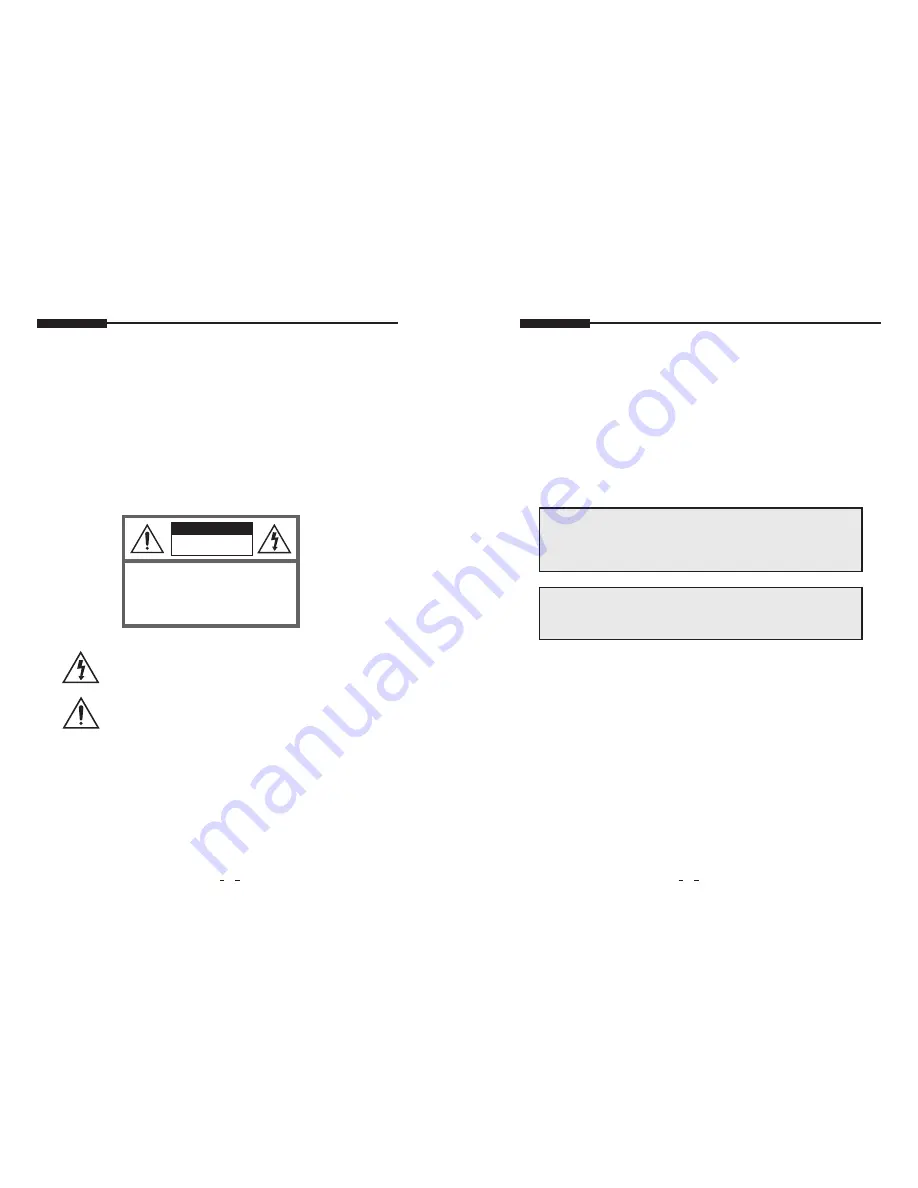
CAUTION

RISK OF ELECTRIC SHOCKS

DO NOT OPEN

CAUTION:

 TO REDUCE THE RISK OF ELECTRIC 

SHOCK, DO NOT REMOVE COVER (OR BACK). 

NO USER SERVICEABLE PARTS INSIDE. REFER 

SERVICING  TO  QUALIFIED  SERVICE  PER-

SONNEL.

This symbol is intended to alert the user to the presence of uninsulated

“dangerous voltage” within the product’s enclosure that may be of suffcient

magnitude to constitute a risk of electric shock to persons.

This symbol is intended to alert the user to the presence of important

operating and maintenance(servicing) instructions in the literature

accompanying the appliance.

CAUTION TO SERVICE PERSONNEL

POWER SUPPLY CORD IS USED AS MAIN POWER DISCONNECT DEVICE IN THIS PRODUCT.
UNPLUG THIS PRODUCT FROM THE WALL OUTLET BEFORE REMOVING THE BACK COVER 
AND SERVICING

EMISSION CHARACTERISTICS TESTED BY SEMKO

THIS PRODUCT HAS BEEN TESTED AND HAS SHOWN COMPLIANCE WITH THE NATIONAL 
SPECIFICATIONS SUCH AS SWEDISH MPR 1990. 10. (MPR 

)

Summary of Contents for STM-32L

Page 1: ...LCD Monitor product Before attempting to connect or operate this product please read the instructions contained in this manual carefully Please save this instruction manual for future reference 42inch Security LCD Monitor STM 42L Instruction Manual ENGLISH ...

Page 2: ...gs convenience receptacles and the point where they exit from the apparatus 11 Only use attachment accessories specified by the manufacturer 12 Use only with the cart stand tripod bracket or table specified by the manufacturer or sold with the apparatus When a cart is used use caution when moving the cart apparatus combination to avoid injury from tip over 13 Unplug this apparatus during lightning...

Page 3: ...e provided on the cabinet to prevent the temperature from rising Do not cover the unit or place anything on the top of unit AVOID HEAT Avoid placing the unit in direct sunshine or near a heating appliance TO ELIMINATE EYE FATIGUE Do not use the unit against a bright back ground and where sunlight or other light sources will shine directly on the monitor BE CAREFUL OF HEAVY OBJECT Neither the monit...

Page 4: ...A BACK PANEL CONTROL 1 HDMI IN 2 DVI IN 3 PC VGA IN 4 PC STEREO IN 5 AUDIO OUT 6 COMPONENT IN 7 COMPONENT AUDIO L R IN 8 Trigger Input 9 AV 1 IN Composite signal input for AV 1 10 AV 1 OUT Video looping out for AV 1 11 AV 2 IN Composite signal input for AV 2 12 AV 2 OUT Video looping out for AV 2 13 S VIDEO IN Y C separated signal input 14 S VIDEO OUT Y C separated signal looping out 15 AV 2 AUDIO...

Page 5: ...ure Sharpness Increase or decrease the sharpness of the picture 1 2 3 4 5 6 7 8 9 1 Press the MENU button and then press the up or down button to select the Custom 2 Press the up or down button to select the sub menu 3 Press the left or right button to adjust the picture setting 4 Press the MENU button to save Brightness Increase or decrease the intensity of the image Contrast Increase or decrease...

Page 6: ...the On or Off 4 Press the MENU button to save 1 Press the up or down button to select the 3D Comb 2 Press the right or SOURCE SELECT button 3 Press the up or down button to select the On or Off 4 Press the MENU button to save 1 Press the up or down button to select the Volume 2 Press the left or right button to adjust Volume setting 3 Press the MENU button to save 2 Color Tone 5 Size 3 Mute 1 Pres...

Page 7: ... Color Tone 2 Press the right or SOURCE SELECT button 1 Press the up or down button to select the Custom in the Color Tone 2 Press the Menu button to save 1 Press the up or down button to select the Size 2 Press the right or SOURCE SELECT button 3 Press the up or down button to select the Size option 3 Press the left or SOURCE SELECT button again 4 Press the up or down button to select the Color T...

Page 8: ...ght or left V Position Move image vertically on screen up or down Frequency Adjust the vertical noise of screen image 1 Press the right or SOURCE SELECT button 2 Press up or down button to select the On or Off 3 Press the MENU button to save 1 Press the up or down button to select the Input Source 2 Press the right or SOURCE SELECT button 3 Press the up or down button to select the Source option 4...

Page 9: ...ress the up or down button to select the Swap 2 Press the right or SOURCE SELECT button to swap the main image for the sub one C PIP MENU For HDMI DVI PC Input D SETUP MENU 1 Press the up or down button to select the Input Source 2 Press the right or SOURCE SELECT button 3 Press the up or down button to select the Input Source option 4 Press the MENU button to save 1 Press the right or SOURCE SELE...

Page 10: ...ress the up or down button to select the Trigger 2 Press the right or SOURCE SELECT button Checks the alarm and signal change of external electronic devices DVRs Cameras etc and displays them on the monitoring screen 1 Press the up or down button to select the Trigger Enable 2 Press the right or SOURCE SELECT button 3 Press the up or down button to select the On or Off 4 Press the Menu button to s...

Page 11: ... down button to select the Display Type 2 Press the right or SOURCE SELECT button 3 Press the up or down button to select the Display Type option 4 Press the Menu button to save PIP FULL If the type of image in the trigger input is different with we are watching trigger image will be displayed as a small screen at a corner which you selected in PIP menu Otherwise it will be displayed as a full scr...

Page 12: ... 2 Press the Menu button to save 7 1 Auto switching On Off 7 2 Auto switching Inputs enabled 1 Press the up or down button to select the Time 2 Press the left or right button to adjust the Time setting 3 Press the MENU button to save 1 Press the up down button to select the Image Rotation 2 Press the right or ENTER button Image Rotation support Image Rotation prevents Image persistence The display...

Page 13: ...ton to save 8 1 Image Rotation On Off 8 2 Image Rotation Min Time control 1063 120 655 Pin 1 RED VIDEO Pin 9 Pin 2 GREEN VIDEO Pin10 SIGNAL CABLE DETECT Pin 3 BLUE VIDEO Pin 11 GROUND Pin 4 GROUND Pin 12 SDA for DDC Pin 5 GROUND Pin 13 H SYNC or H V SYNC Pin 6 RED GROUND Pin 14 V SYNC Pin 7 GREEN GROUND Pin 15 SCL for DDC Pin 8 BLUE GROUND D SUB CONNECTOR PIN ASSIGNMENTS Dimension 1 User s Manual ...

Page 14: ...r is comprised of four stages On Green Standby Suspend Active off Red on off 1 sec and Unsupported mode Green POWER CONSUMPTION 230W WXGA 250W WUXGA LED INDICATOR SPECIFICATIONS NOTE Technical specifications are subject to change without notice STM 42L LCD Type 42 DiagonalAM TFT Active Matrix Pixel pitch mm 0 227mm H x 0 681mm V BRIGHTNESS 500cd Typical CONTRAST RATIO 1100 1 Typical VIEWINGANGLE 1...

Page 15: ...heck that the Brightness and or the Contrast adjustments of the Display haver not been turned down to minimum levels Check Input Signal message on screen 1 The signal cable should be completely connected to the video card computer 2 The video card should be completely seated in its slot and the computer is switched ON Display image is not centered too small or toolarge in PC mode Push the down key...

Page 16: ...MEMO MEMO ...

Page 17: ...TEL 82 31 740 8151 8 FAX 82 31 740 8145 SAMSUNG TECHWIN EUROPE CO LTD Samsung House 1000 Hillswood Drive Hillswood Business Park Chertsey Surrey UNITED KINGDOM KT16 OPS TEL 44 1932 45 5300 FAX 44 1932 45 5325 SAMSUNG TECHWIN AMERICA Inc 1480 Charles Willard St Carson CA 90746 UNITED STATES Tol Free 1 877 213 1222 FAX 1 310 632 2195 www samsungcctvusa com SALES NETWORK ...

Reviews: