background image

COLOR CCTV MONITOR

COLOR CCTV MONITOR

User’s Manual

User’s Manual

9

8

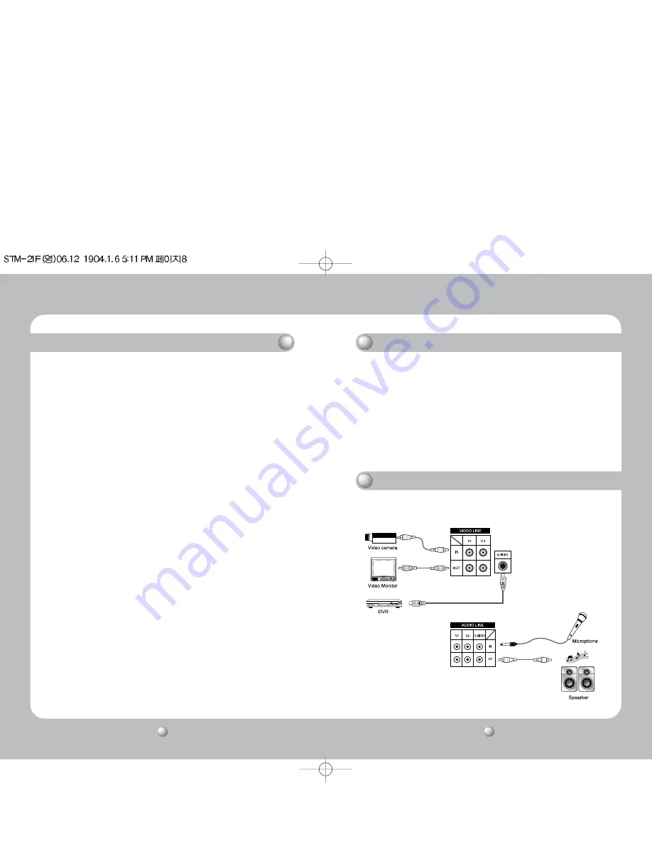
POSSIBLE CONNECTIONS

LOCATION AND OPERATION OF CONTROLS

13~16. VIDEO INPUT & OUTPUT CONNECTORS 

These BNC connectors permit looping of a video signal in those installations where it is
desirable to display the video signal on more than one monitor. A standard 1.0 Vp-p
video signal applied to the VIDEO INPUT will also appear at the VIDEO OUTPUT. Use
coaxial cables with BNC type plugs for these connections.

17. S-VIDEO JACK

If the camera or other video source outputs an S-VIDEO signal, connect it directly to this jack. 

18~23. AUDIO INPUT & OUTPUT CONNECTORS

Connect an RCA cable between these jacks and the audio output jack of a camera or VCR.

• Read the installation/operation manual thoroughly before connecting equipment.
• Turn off the power source before connecting the monitor and external equipment.

1. TINT

Adjust the TINT control for the proper color phase or flesh tones. When turned
counterclockwise, the skin tone becomes reddish. When turned clockwise, skin tone
becomes greenish.

2. SHARPNESS

Adjust the SHARPNESS control to obtain the clearest picture.

3. COLOR

Adjust the COLOR control to set the color saturation level. Turn the control clockwise to
increase and counterclockwise to decrease.

4. BRIGHTNESS

Adjust the BRIGHTNESS control for the desired overall display brightness. This control is
also useful to compensate for differences in area lighting. Turn the control clockwise to
increase and counterclockwise to decrease.

5. CONTRAST

Adjust the CONTRAST control for the desired overall contrast. Proper adjustment will allow
maximum gradations between the darkest and lightest picture areas. Turn the control
clockwise to increase and counterclockwise to decrease.

6. VOLUME

Adjust the VOLUME control for the desired audio level. Turn the control clockwise to
increase and counterclockwise to decrease.

7. VIDEO 1 TACT SWITCH 

Set the switch to VIDEO 1 if the camera jack is used.

8. VIDEO 2 TACT SWITCH 

Set the switch to VIDEO 2 if the camera jack is used.

9. S-VIDEO TACT SWITCH

Set the switch to S-VHS if the S-VIDEO jack is used.

10. POWER SWITCH

Press to turn the monitor ON. The POWER LAMP above the switch will illuminate.

11. POWER LED LAMP

Power lamp indicates the power is on.

12. AC INLET

Use 100-240V  AC, 50/60 Hz.
To prevent electrical shocks and fire hazards, do not use any other power source.

LOCATION AND OPERATION OF CONTROLS

Summary of Contents for STM-21F

Page 1: ... ELECTRONICS UK LTD Samsung House 1000 Hillswood Drive Hillswood Business Park Chertsey Surrey KT16 OPS TEL 44 1932 45 5308 FAX 44 1932 45 5325 SALES NETWORK Thank you for purchasing a SAMSUNG CCTV MONITOR Before attempting to connect or operate this product please read these instructions carefully and save this manual for future use ENGLISH CCTV COLOR FLAT MONITOR STM 21F User s Manual Clear Flat...

Page 2: ... A digital device pursuant to part 15 of the FCC Rules These limits are designed to provide reasonable protection against harmful interference when the equipment is operated in a commercial environment This equipment generates uses and can radiate radio frequency energy and if not installed and used in accordance with the instruction manual may cause harmful interference to radio communications Op...

Page 3: ... safety If the provided plug does not fit into your outlet Consult an electrician for replacement of the obsolete outlet 10 Protect the power cord from being walked on or pinched particularly at plugs convenience receptacles and the point where they exit from the apparatus 11 Only use attachments accessories specified by the manufacturer 12 Use only with the cart stand tripod bracket or table spec...

Page 4: ...hecked by qualified personnel before operating it any further Unplug the unit from the wall outlet if it is not going to be used for several days or more To disconnect the cord pull it out by the plug Never pull the cord itself Allow adequate air circulation to prevent internal heat buildup Do not place the unit on surfaces rugs blankets etc or near materials curtains draperies that may block the ...

Page 5: ...in the clearest picture 3 COLOR Adjust the COLOR control to set the color saturation level Turn the control clockwise to increase and counterclockwise to decrease 4 BRIGHTNESS Adjust the BRIGHTNESS control for the desired overall display brightness This control is also useful to compensate for differences in area lighting Turn the control clockwise to increase and counterclockwise to decrease 5 CO...

Page 6: ...n an unstable cart stand tripod bracket or table Do not drop 6 VENTILATION Slots and openings in the cabinet are provided for ventilation To ensure reliable operation of this monitor and to protect it from overheating the openings must not be blocked or covered This monitor should never be placed near or over a radiator or heat register or in a built in installation such as a bookcase or rack unle...

Reviews: