


Alignment and Adjustments
Samsung Electronics
4-17
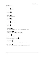
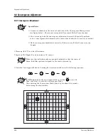
1. Select the “DYNAMIC” video mode.
2. Warm up the set at least for 10 minutes.
3. Enter the Convergence mode by pressing the remote control buttons in the following sequence :
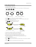
4. Set the Beam Alignment Adjustment CY to Zero magnetic field area.
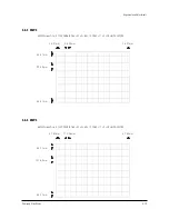
5. Check the squarewave at the point where the focus is misaligned.
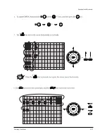
6. Press the button on the remote control during 3~5 sec and vibrating dot-pattern appears.
7. Adjust the Focus-pack VR for defocusing.
8. Mute the other patterns (R/B) other than G-PATTERN.
(Use / buttons on the remote control.)
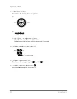
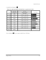
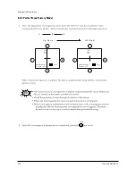
9. Adjust the 2, 4 polarities of VM-COIL as shown in figure below.
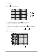
10. Adjust the G-Focus until any light around the core disappears.
11. Adjust G-Focus so that the surrounding flash can disappear from the spot.
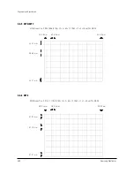
12. After G-Focus adjustments are complete, adjust R-Focus as above procedures.
13. The B-CRT adjustments can be omitted because the variance of beam focus is small.
(Only Vm-coil is mounted.)
14. Adjust the Focus-pack VR for fine focusing.
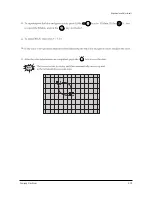
15. Press the button on the remote control, and the mode changes to the Convergence Adjustment
mode.
16. Press the button on the remote control to return to normal viewing.
(Creation of CPM Zero Magnet)
(Creation of the 2-pole/4-pole zero magnets)
G-FOCUS
CORE
(Varying G-Focus Pack)
Varying the 2-pole of VM
(Positioning the Core in the Center)
Varying the 4-pole of VM
CORE
G-FOCUS
(When VM 2-Pole Adjustment is completed)
(Adjust until the light around
the core becomes a circle)
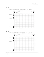
4-5 Beam alignment Adjustments
Mute
TV
S.STD
Summary of Contents for SP43T7HPS
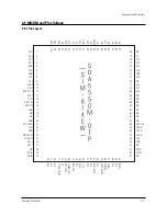
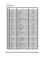
Page 10: ...Reference Information Samsung Electronics 2 5 2 3 MICOM IIC BUS LINE UP MSP3452G Option ...
Page 39: ...Alignment and Adjustments Samsung Electronics 4 27 Mute Menu Menu TV TV P Size or or ...
Page 40: ...Alignment and Adjustments 4 28 Samsung Electronics LINE Adjust VOL P Menu S Mode ...
Page 41: ...Alignment and Adjustments Samsung Electronics 4 29 TV 12 13 14 15 S Mode ...
Page 75: ...Schematic Diagrams 10 2 Samsung Electronics TP04 TP03 TP05 10 2 MAIN 2 TP03 TP04 TP05 ...
Page 76: ...Samsung Electronics Schematic Diagrams 10 3 10 3 MAIN 3 TP06 TP07 TP06 TP07 ...
Page 78: ...Samsung Electronics Schematic Diagrams 10 5 10 5 MICOM ...
Page 79: ...Schematic Diagrams 10 6 Samsung Electronics 10 6 CRT ...
Page 80: ...Samsung Electronics Schematic Diagrams 10 7 10 7 SUB 1 TP21 TP21 ...
Page 81: ...Schematic Diagrams 10 8 Samsung Electronics 10 8 SUB 2 TP22 TP23 TP22 TP23 ...
Page 82: ...Samsung Electronics Schematic Diagrams 10 9 10 9 SUB 3 ...
Page 83: ...Schematic Diagrams 10 10 Samsung Electronics 10 10 CONVERGENCE SDC12 1 ...
Page 84: ...Samsung Electronics Schematic Diagrams 10 11 10 11 CONVERGENCE SDC12 2 ...
Page 85: ...Schematic Diagrams 10 12 Samsung Electronics 10 12 PRO SCAN 1 ...
Page 86: ...Samsung Electronics Schematic Diagrams 10 13 10 13 PRO SCAN 2 ...
Page 87: ...Schematic Diagrams 10 14 Samsung Electronics 10 14 AV FRONT ...
Page 88: ...Samsung Electronics Schematic Diagrams 10 15 10 15 VM ...
Page 89: ...Schematic Diagrams 10 16 Samsung Electronics 10 16 CONTROL ...
Page 90: ...Samsung Electronics Schematic Diagrams 10 17 10 17 DY JACK SENSOR DY JACK SENSOR ...


