Samsung SGH-I750 Series, Service Manual
The Samsung SGH-I750 Series offers an incredible user experience with its cutting-edge technology and sleek design. Discover every feature and function of your device by accessing our comprehensive user manual. Download it for free at manualshive.com and harness the full potential of your Samsung SGH-I750 Series.
Share
Download


Reviews:
No comments
Related manuals for SGH-I750 Series

Flexor 500
Brand: Camrivox Pages: 4
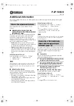
PJP-100UH
Brand: Yamaha Pages: 3

YotaPhone
Brand: Yota Pages: 104

SIP-T23P
Brand: Yealink Pages: 3

FRV506
Brand: G53 Limited Pages: 10

SIP-T21
Brand: Yealink Pages: 143

iNQ1
Brand: INQ Pages: 101

Augusta H375i
Brand: SouthernLINC Pages: 63

Octa-A41
Brand: iBall Slide Pages: 63

SND251
Brand: SENDO Pages: 54

SIP DECT Series
Brand: Teledex Pages: 1

cymbal Z-320
Brand: Zte Pages: 99

3000 5330
Brand: Mitel Pages: 29

WirelessIP 3000
Brand: Hitachi Cable Pages: 132

R239
Brand: Zte Pages: 33

N860
Brand: Zte Pages: 108

N9511
Brand: Zte Pages: 84

G150I
Brand: G-Tide Pages: 24


