


SAMSUNG Proprietary-Contents may change without notice
Exploded View and Parts List
2-9
This Document can not be used without Samsung's authorization
5
8
7
6
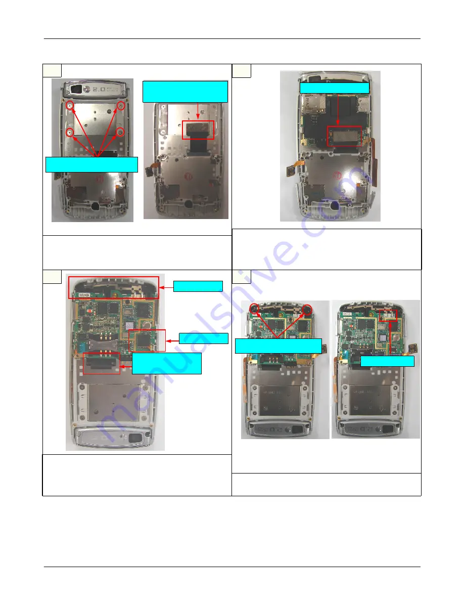
1) Insert "3*4 key PCB" to the connector in PBA.
2) Flatten F-PCB by finger while open and close
slide.
3) Insert the Antenna module.
1) Screw the 2 Bolts.[Figure 1]
2) As seen figure 2, soldering the antenna module.
1) After combine Front Cover, the 4 Bolts.
[Figure 1]
2) Attach "electric conduction sponge" on connector.
[Figure 2]
1) Insert "F-PCB" to the connector in PBA.
※
caution
1) Connector should be certainly clicked along the
marked line.
F-PCB Connector
Screw(1.4*1.1)
Torque:0.9±0.1Kgf
ㆍ
Cm
Electric conduction
Sponge
< Figure 1 >
< Figure 2 >
Intenna
Connector
Flatten
by finger.
Screw (1.4*4)
Torque:1.0±0.1Kgf
ㆍ
Cm
Soldering
< Figure 1 >
< Figure 2 >


