Samsung SGH-C210, Service Manual
The Samsung SGH-C210 Service Manual is a comprehensive guide that provides users with step-by-step instructions on operating and maintaining their device. This essential manual can be downloaded for free from our website, enabling users to easily access and enhance their Samsung SGH-C210 experience.
Share
Download


Reviews:
No comments
Related manuals for SGH-C210

6755i
Brand: Aastra Pages: 2

6755i
Brand: Aastra Pages: 2

Sunny V38
Brand: E-Boda Pages: 50

Joy Plus
Brand: Olympia Pages: 52

Xda Flame
Brand: O2 Pages: 36
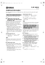
PJP-100UH
Brand: Yamaha Pages: 3

Fun 70 BT
Brand: Hama Pages: 14

T42
Brand: Yealink Pages: 2
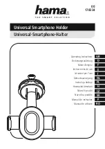
178334
Brand: Hama Pages: 27

5380ip
Brand: Aastra Pages: 24

C790
Brand: Pantech Pages: 66

SMARTPHONE 3.2 LITE
Brand: Tesla Pages: 3

Urbano L02
Brand: AU Pages: 72

VVX 411
Brand: Polycom Pages: 2

DVC-1100
Brand: D-Link Pages: 13

09
Brand: Huawei Pages: 14

ANG-LX2
Brand: Huawei Pages: 50

AMN-LX2
Brand: Huawei Pages: 68


