


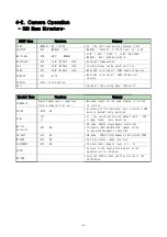


4-2. Camera Operation
- OSD Menu Structure-
SETUP Menu
Function
Summary
LENS
ㆍMANUAL ㆍDC / VIDEO
* DC : The IRIS level can be adjusted.(1~70)
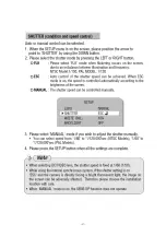
SHUTTER
ㆍESC
ㆍMANUAL ㆍFLK
* MANUAL : 1/60(50) ~ 1/120,000 sec, x2 ~ x128
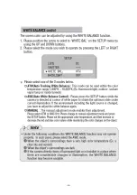
WHITE BAL.
ㆍATW
ㆍAWC
ㆍMANUAL
* ATW : 1,800 ~ 10,500°K
*AWC : ONE PUSH
* MANUAL : RED / BLUE Adjustable.
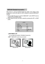
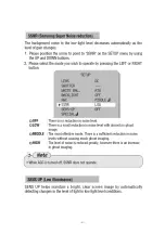
BACKLIGHT
ㆍOFF
ㆍLOW ㆍMIDDLE ㆍHIGH
* Backlight compensation.
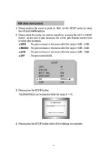
AGC
ㆍOFF
ㆍLOW ㆍMIDDLE ㆍHIGH
* The Brightness can be adjusted.(1~70)
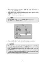
SSNR
ㆍOFF
ㆍLOW ㆍMIDDLE ㆍHIGH
* When AGC is turned off, SSNR does not operate.
SENS-UP
ㆍOFF
ㆍAUTO
* When AGC is turned off, SENS-UP does not
operate.
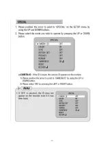
SPECIAL
Refer to the bottom.
EXIT
* Saved all the setting menu, then exits.
Special Menu
Function
Summary
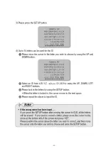
CAMERA ID
English uppercase or lowercase
letters /numeral 0~9/-,null
* Maximum length for the name display is limited
15 letters.
COLOR
ㆍAUTO ㆍON
* According to the luminance level, electronic D&N
mode is automatically switched.
SYNC
ㆍINT
ㆍLL
* LL : You can adjust desired phase from 0˚~ 359˚
* Trigger Signal : Auto Detection
Motion
Detection
ㆍOFF
ㆍON
* ON mode: AREA(4 Programmable zone/SIZE)
* The words "MOTION DETECTED" appear on the
screen when movement is detected.
PRIVACY
ㆍOFF
ㆍON
* ON mode : AREA(4 Programmable 4 Zone)/SIZE/TONE
MIRROR
ㆍOFF
ㆍON
* Set a horizontal image inversion.
SHARPNESS
ㆍOFF
ㆍON
* The available range of level is 0 ~ 31.
RESET
* Returns to the level which was set by the
manufacturer for shipment.
RETURN
* Save the SPECIAL menu and then returns to the
SETUP menu.
-23-
Summary of Contents for SDC-313ANA
Page 1: ...SDC 415 Series Service Manual 1 ...
Page 4: ...1 Specification and Feature 1 1 Specifications 1 2 Features 1 3 Components 4 ...
Page 7: ...1 2 Features 7 ...
Page 8: ...1 3 Components 8 ...
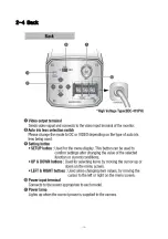
Page 9: ...2 Name and Functions of Parts 2 1 Front 2 2 Side 2 3 Bottom 2 4 Back 9 ...
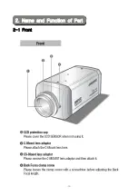
Page 10: ...2 1 Front 2 Name and Function of Part 10 ...
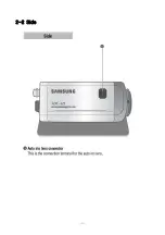
Page 11: ...2 2 Side 11 ...
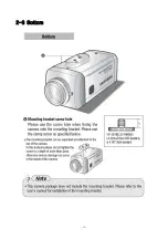
Page 12: ...2 3 Bottom 12 ...
Page 13: ...2 4 Back 13 ...
Page 15: ...3 1 Connecting to Lens 3 Connection 15 ...
Page 16: ... 16 ...
Page 17: ... 17 ...
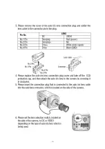
Page 18: ...3 2 Connecting to Monitor 18 ...
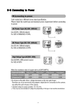
Page 19: ...3 3 Connecting to Power 19 ...
Page 20: ...4 Instrument Camera Operation 4 1 Instrument 4 2 Camera Operation 20 ...
Page 24: ... 24 ...
Page 25: ... 25 ...
Page 26: ... 26 ...
Page 27: ... 27 ...
Page 28: ... 28 ...
Page 29: ... 29 ...
Page 30: ... 30 ...
Page 31: ... 31 ...
Page 32: ... 32 ...
Page 33: ... 33 ...
Page 34: ... 34 ...
Page 35: ... 35 ...
Page 36: ...SDC 415 ONLY 36 ...
Page 37: ... 37 ...
Page 38: ... 38 ...
Page 45: ...5 5 PCB LAYOUT 5 5 1 SDC 415 313A TYPE PORCESS PCB COMPONENT SILK 45 ...
Page 46: ...5 5 1 SDC 415 313A TYPE PROCESS PCB SOLDER SILK 46 ...
Page 47: ...5 5 2 SDC 313B TYPE PROCESS PCB COMPONENT SILK 47 ...
Page 48: ...5 5 2 SDC 313B TYPE PROCESS PCB SOLDER SILK 48 ...
Page 49: ...5 5 3 SDC 415 313 TYPE MOTHER PCB COMPONENT SILK 49 ...
Page 50: ...5 5 3 SDC 415 313 TYPE MOTHER PCB SOLDER SILK 50 ...
Page 51: ...5 5 4 SDC 415 313N D TYPE BACK PCB COMPONENT SILK 51 ...
Page 52: ...5 5 4 SDC 415 313N D TYPE BACK PCB SOLDER SILK 52 ...
Page 53: ...5 5 5 SDC 415PH TYPE BACK PCB COMPONENT SILK 53 ...
Page 54: ...5 5 5 SDC 415PH TYPE BACK PCB SOLDER SILK 54 ...


