background image

_ setup

setup

NIGHT

DAY DWELL TIME : Time required to determine the filter switch.

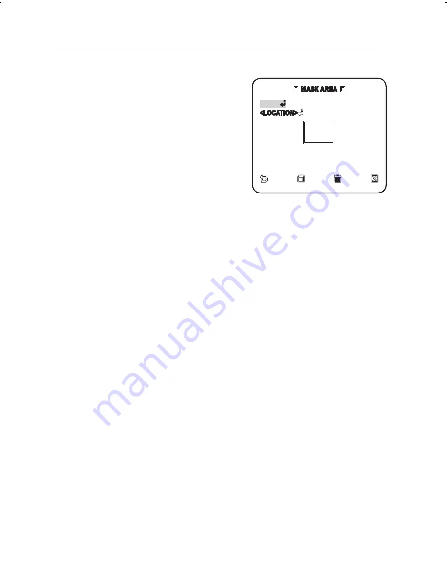
MASK AREA : If there exists a bright 

spot light source in a night scene, you 

can specify the size and position as 

needed. 

This will prevent an error in switching 

filter, or failure to determine the filter 

switch in a night scene where a bright 

spot light source exists. 

Any excessively bright area in a night 

scene will be MASKed.

You can specify MASK 1 and 2 simultaneously.

If <

BACKLIGHT

> is set to <

BLC

>, the MASK AREA function is not available.

EXT : The interface to an external alarm enables an automatic switch between 

DAY and NIGHT mode. 

If you set <

DAy/NIGHT

> to EXT, and alarm #1 to NO/NC in ALARM SET-

ALARM IN SET, the alarm can be used for an input signal in EXT mode of 

<

DAy/NIGHT

>. 

If an alarm signal occurs, the mode will switch to NIGHT.

If <

DAY/NIGHT

> is set to EXT, ALARM1 in ALARM OUT SET, and ALARM1 in ALARM 

SET-AUTO SET are not available.
If you use an infrared light source while in AUTO mode, this may cause a failure in 
AUTO SWITCH or AUTO FOCUS.

-
-


M

  MASK AREA  

<SIZE>

<LOCATION>

Z6806125101A-SCP-2430(P)-ENGLISH28   28

2010-07-21   오후 6:05:45

Summary of Contents for SCP-2250(P)

Page 1: ...Smart Dome Camera User Manual SCP 2430 P ...

Page 2: ... appliance to rain or moisture To prevent injury this apparatus must be securely attached to the floor wall in accordance with the installation instructions Use only the 24V 60Hz AC adaptor for power supply WARNING Be sure to use only the standard adapter that is specified in the specification sheet Using any other adapter could cause fire electrical shock or damage to the product Incorrectly conn...

Page 3: ...e normally contact the nearest service center Never disassemble or modify this product in any way SAMSUNG is not liable for problems caused by unauthorized modifications or attempted repair When cleaning do not spray water directly onto parts of the product Doing so may cause fire or electric shock Do not expose the product to the direct airflow from an air conditioner Otherwise it may cause moist...

Page 4: ...ge to the product Keep out of direct sunlight and heat radiation sources It may cause fire Install it in a place with good ventilation Avoid aiming the camera directly towards extremely bright objects such as sun as this may damage the CCD image sensor Apparatus shall not be exposed to dripping or splashing and no objects filled with liquids such as vases shall be placed on the apparatus The Mains...

Page 5: ...are designed to provide reasonable protection against harmful interference when the equipment is operated in a commercial environment This equipment generates uses and can radiate radio frequency energy and if not installed and used in accordance with the instruction manual may cause harmful interference to radio communications Operation of this equipment in a residential area is likely to cause h...

Page 6: ...tect the power cord from being walked on or pinched particularly at plugs convenience receptacles and the point where they exit from the apparatus Only use attachments accessories specified by the manufacturer Use only with the cart stand tripod bracket or table specified by the manufacturer or sold with the apparatus When a cart is used use caution when moving the cart apparatus combination to av...

Page 7: ...tallation 10 Installation 14 Initial Setup 17 Connecting with Other Device Setup 20 20 How to use the Keyboard Controller 21 Main Menu 22 Profile 24 Camera Set 33 Intelligent Video 35 Privacy Zone 36 Preset 38 Auto Set 42 Zone Set 43 Alarm Set 45 Clock Set 45 Other Set 47 Communication 48 System Info Appendix 49 49 Shortcut Keys 50 Specifications 52 Product Appearance ...

Page 8: ... into the black and white mode at night or in the environment with low illumination White Balance to control the brightness to the illumination Backlight Compensation under spotlight or utmost bright illumination Auto Focus to automatically adjust the focus to the subject movement Privacy zone to hide a specific area for personal privacy PAN TILT for precise control at high speed What s Included P...

Page 9: ...lish _ overview At a Glance CAMERA FRAME SET Wipe out a dirty surface of the lens softly with a lens tissue or cloth to which you have applied ethanol M LENS HOOK HOOK ALARM IN ALARM OUT RS 485 POWER INPUT ...

Page 10: ... then attach the template on the desired location on the ceiling When installing the frames set align all template s screw holes and those of the frames set This template prevents dust entering from the ceiling into the camera assembly Installation Press the SNAP FIT on the ADAPTOR to open the ADAPTOR and arrange cables so they pass out of the FRAME SET 1 EXTERNAL CABLES FRAME SET FRAME SET ADAPTO...

Page 11: ...ET and close the ADAPTOR Then wrap the BNC JACK with the INSULATION TUBE and use an insulation tape to seal up the end of the INSULATION TUBE so that the BNC JACK does not protrude outside of the INSULATION TUBE coating For more information about cable connection refer to Connecting the adaptor cable page 19 2 3 M FRAME SET ADAPTOR SNAP FIT INSULATION TUBE BNC JACK ALARM OUT ALARM IN RS 485 POWER ...

Page 12: ...n either end of the CAMERA in the RACK direction of the FRAME SET to secure the two Then ensure that all of the two HOOKS clicks to fix to the RACK properly When the installation is completed remove the PROTECTIVE FILM and PROTECTIVE TAPE from on the lens 4 M FRAME SET 22P CONNECTOR CAMERA SAFETY WIRE BRACKET WIRE FRAME SET CAMERA RACK HOOK RACK HOOK CAMERA FRAME SET PROTECTIVE FILM PROTECTIVE TAP...

Page 13: ...the COVER clockwise As shown in the figure below turn it until you see the BUTTON hole and hear a click Ensure that the COVER should not move any further if you turn the COVER counter clockwise If you want to remove the COVER hold down the BUTTON and turn the COVER counter clockwise to remove the COVER 5 FRAME SET BUTTON CAMERA COVER COVER BUTTON COVER ...

Page 14: ...w Communication Protocol Setup Use pins 1 4 of SW603 to specify the communication protocol PIN Comp PIN1 PIN2 PIN3 PIN4 PIN7 A OFF OFF OFF OFF OFF B ON OFF OFF OFF OFF C OFF ON OFF OFF OFF D ON ON OFF OFF OFF E OFF OFF ON OFF OFF ON OFF ON OFF OFF OFF ON ON OFF OFF H ON ON ON OFF OFF I OFF OFF OFF ON OFF J ON OFF OFF ON OFF OFF ON OFF ON OFF ON ON OFF ON OFF OFF OFF ON ON OFF N ON OFF ON ON OFF O ...

Page 15: ...e map when Controller and RS 422A RS 485 is connected it should be terminated according to the Cable feature of impedance on the each end of the transmitting line to transfer the signals in long distance by controlling the reflection of the signals to the lowest Termination Using numbers 1 and 2 PIN turn to ON and it will be terminated Controller Termination n 32 Termination SW1 ON CAM n CAM n 1 C...

Page 16: ...nnection A communication error may occur if you connect multiple cameras that are assigned the same address in the network M Controller Termination n 32 Termination SW1 ON SW2 ON CAM n CAM n 1 CAM 2 CAM 1 RS 422A RS 485 Full Duplex Organization ...

Page 17: ...onitor Connect one end of the BNC video cable connector to the Video Output Terminal VIDEO OUT Connect the other end of the connector to the Video Input Terminal of the monitor 1 2 Video terminal on the rear of monitor BNC Cable MONITOR ALARM IN POWER SOURCE ALARM OUT CONTROLLER DVR ...

Page 18: ... line to a corresponding ALARM OUT port of the monitor Connect the other end of the signal line to the common COM port To connect the controller Connect an external controller or DVR to the camera with which you can adjust the camera Connect the Rx pin of the camera to the Tx pin of the controller Connect the Rx pin of the camera to the Tx pin of the controller Connect the Tx pin of the camera to ...

Page 19: ...g the adaptor cable Power Supply Connect the cables as necessary and turn on the camera to check if it works properly Connect the adaptor to the power terminal of the camera Plug the power cord of the adaptor into the wall outlet 1 2 Adaptor Board ...

Page 20: ...ves your settings and returns to the previous screen HOME Returns to the main menu SAVE Use this icon if you want to save your settings after you specified the mask area and privacy area etc Once you saved your settings the changes remain intact even if you select QUIT on exit DEL Use this icon if you want to delete a mask or privacy area etc Once you deleted your settings the deletions remain val...

Page 21: ... can set the PRESET POSITION and DURATION AUTO SET Contains sub menu items of AUTO PAN PATTERN and SCAN ZONE SET You can set the standard azimuth and zone area for the camera ALARM SET You can set the alarm priority and I O sequence CLOCK SET You can set the display time and format OTHER SET You can set preferred language reset the system and select an OSD color to your preference COMMUNICATION Co...

Page 22: ...bject even in a severe backlight scene DAY NIGHT Automatically optimizes the camera settings to the day and night scene GAMING This automatically configures the settings so that you can work in a stable illumina tion condition as indoors CUSTOM Your change to any of the PROFILE settings will switch the display to CUSTOM CAMERA SETUP MENU STANDARD ITS BACKLIGHT DAY NIGHT GAMING Parent Menu Sub menu...

Page 23: ...T OFF ON OFF OFF OFF EXT BURST OFF ON OFF OFF OFF WHITE BAL DAY DAY NIGHT DAY DAY NIGHT DAY DAY MODE ATW2 ATW1 ATW1 ATW1 ATW1 RED 0 0 0 0 0 BLUE 0 0 0 0 0 NIGHT BRIGHTNESS Custom Setting MEDIUM Custom Setting MEDIUM Custom Setting MODE OFF ATW2 OFF ATW2 OFF RED Custom Setting 0 Custom Setting 0 Custom Setting BLUE Custom Setting 0 Custom Setting 0 Custom Setting DETAIL 2 2 2 2 2 ...

Page 24: ...fer to How to use the keyboard controller page 20 Select CAMERA SET CAMERA ID Use the joystick to select a desired character then press ENTER In the lower input box of the screen the selected character will be entered You can enter up to 54 characters including alphabets numbers and special characters LOCATION Specify the display position of the camera ID When done press ENTER The camera ID will b...

Page 25: ...the signal strength falls below the standard level AGC will amplify the video signal to automatically improve the sensitivity If SENS UP is set to OFF or FIX mode the MOTION menu will switch to AGC With the USER submenu selected press ENTER to display the corresponding screen In this mode you can select from VERY LOW to VERY HIGH in 16 levels enabling deeper wider choices to your convenience With ...

Page 26: ...he level is the greater the effect is Set it to USER to specify the level SHUTTER You can select a fixed fast electronic shutter speed in 7 options ranging from 1 100 to 1 10k which is mostly used to take a picture of a fast moving object As long as SENSE UP is set to AUTO FIXED FLICKERLESS to ON the SHUTTER menu is not available SENS UP Automatically senses the darkness level at night or in a low...

Page 27: ...set options as appropriate DAY Fixed to DAY mode regardless of the scene NIGHT Fixed to NIGHT mode regardless of the scene If BURST is set to ON the burst signal will be output along with the black and white composite video signal AUTO According to the luminance this will switch DAY to NIGHT mode or vice versa BURST If set to OFF the burst signal will not be output in NIGHT mode DAY NIGHT BRIGHTNE...

Page 28: ...MASK 1 and 2 simultaneously If BACKLIGHT is set to BLC the MASK AREA function is not available EXT The interface to an external alarm enables an automatic switch between DAY and NIGHT mode If you set DAY NIGHT to EXT and alarm 1 to NO NC in ALARM SET ALARM IN SET the alarm can be used for an input signal in EXT mode of DAY NIGHT If an alarm signal occurs the mode will switch to NIGHT If DAY NIGHT ...

Page 29: ...ge of the color temperature to correct the WHITE BAL as needed The following color temperature ranges are assured in individual modes ATW1 2500K 9300K 1 ATW2 2000K 10000K suitable to sodium light source 2 1 With ATW1 mode active in a color temperature environment ranging beyond between 2500K and 9300K a proper white balance value may not be produced if this is the case you are recommended to use A...

Page 30: ...ording to your settings According to the specified recording mode select a WHITE BAL mode with necessary options ATW1 2 The camera can automatically adjust the color temperature in real time according to the ambient conditions Color temperature range 1 2500K 9300K 2 2000K 10000K AWC Pressing ENTER on a desired item will perform ATW once You can set the R GAIN B GAIN value 3200K Set the color tempe...

Page 31: ...eet light ONEAF Restores focus after the operation of pan tile zoom and operates the same as in MF unless the operation of pan tile zoom is executed MF You can adjust the focus manually While you are working on the following objects AF may not work properly If this is the case use MF instead Very bright object or dominant object in a dark scene Object against the rear side of a moist or dirty glas...

Page 32: ...adjust the vertical and horizontal distinction respectively V SYNC You can set the V SYNC mode If you select INT the camera will use the internal synchronization If selecting LINE the camera will use an external power frequency for synchronization The LL PHASE can be adjusted as appropriate AGC COLOR SUP You can adjust the color reproduction range according to AGC REVERSE You can reverse the video...

Page 33: ...n the following images Single colored flat image Low contrast scene High frequency image taken under a fluorescent lamp Regular patterned image Intelligent Video You can enable the motion detection and tracking functions For selecting and saving each menu item refer to How to use the keyboard controller page 20 Select MAIN MENU INTELLIGENCE Select each item and set appropriately MOTION You can ena...

Page 34: ...to move in the same position When a newly appearing object conceals another object that is moving MASK AREA Select the number of the area to be masked that will be excluded from motion detection Select the mask number and set the mask size and its coverage DISPLAY When selected ON it displays the motion detected and detection of configured advanced function SENSITIVITY Sets the sensitivity of moti...

Page 35: ...ss ENTER The Privacy zone would be marked each time you press ENTER Use the joystick to set the position of each point top left top right bottom right bottom left and press ENTER Position setting is completed Save the changes and move to the previous screen and select the STYLE Select the COLOR and pick a desired color Setting one or more privacy zone and enabling privacy function will disable the...

Page 36: ...ET Select the preset number Select POSITION and adjust PAN TILT ZOOM to the desired setup using the joystick Set PRESET ID to ON and enter the name For entering the name refer to CAMERA ID page 24 1 2 3 4 MAIN MENU PROFILE CAMERA SET INTELLIGENCE PRIVACY ZONE PRESET AUTO SET ZONE SET ALARM SET CLOCK SET OTHER SET PRESET 0 1 2 3 4 5 6 7 8 9 10 11 12 13 14 15 16 17 18 19 20 21 22 23 24 25 26 27 28 2...

Page 37: ...fer to CAMERA SET pages 24 33 The preset position can be specified for a tilt range of between 6 and 90 Those presets that are out of a tilt of 90 can not be specified If you try to specify a preset position for a range exceeding a tilt of 90 using a controller SSC 1000 2000 or 5000 you will see a message of SET AGAIN on the screen If this is the case try again for a range below a tilt of 90 If yo...

Page 38: ...tion Auto Pan Setup Set the starting and ending positions to patrol between points at specified speed For selecting and saving each menu item refer to How to use the keyboard controller page 20 Select MAIN MENU AUTO SET Select the number of AUTO PAN AUTO PAN setup screen appears M 1 2 MAIN MENU PROFILE CAMERA SET INTELLIGENCE PRIVACY ZONE PRESET AUTO SET ZONE SET ALARM SET CLOCK SET OTHER SET AUTO...

Page 39: ...60 endlessly while stops for the DWELL TIME at both positions SPEED Sets the moving speed of the camera from 1 to 64 DWELL TIME Sets the dwell time at the starting and ending positions from 1 to 60 seconds Pattern Setup You can manually record your pan tilt zoom movements to a monitoring pattern for up to 2 minutes For selecting and saving each menu item refer to How to use the keyboard controller...

Page 40: ...enu item refer to How to use the keyboard controller page 20 Select MAIN MENU AUTO SET Select the scan number SCAN setup screen appears Move the cursor to a number with the mark which contains a defined preset Press ENTER S mark appears beside the and the corresponding preset is included in the scan SCAN numbers configured for a certain page can be saved only in the corresponding page Make sure to...

Page 41: ... between 1 4 for SCAN or AUTO PAN 1 3 for PATTERN and 0 511 for PRESET PLAY NUMBER Sets the number of the defined auto play operation AUTO PLAY2 Select the auto play action and set its starting ending time When the time hits the defined starting time configured auto play will begin You can set between 1 4 for SCAN or AUTO PAN 1 3 for PATTERN and 0 511 for PRESET 1 2 AUTO PLAY 1 AUTO RETURN 1MIN AU...

Page 42: ...t the north direction which will be the reference for all other directions Set ZONE AREA SET to ON When the ZONE AREA MAP screen appears select a number When the ZONE AREA SET screen appears set the POSITION and ZONE ID SET For entering the name refer to CAMERA ID page 24 POSITION Sets the left right boundaries of the zone 1 2 3 4 5 6 ZONE SET AZIMUTH OFF ZONE AREA SET OFF MAIN MENU PROFILE CAMERA...

Page 43: ...y ALARM PRIORITY Sets the priorities of alarms Setting the priorities of 8 alarms defines the alarm notification priorities of them in the highest orders By default the priorities are set as Alarm 1 Alarm 2 Alarm 8 When multiple alarms are generated at the same time alarm notifies in the order of the default priority setting While an alarm is generating no motion is detected 1 2 ALARM SET ALARM PR...

Page 44: ...to OFF will discard with the pattern or scan action after moving to the preset position PATTERN 1 3 Defined pattern action HALF1 Patterns 1 and 2 in serial action HALF2 Patterns 2 and 3 in serial action WHOLE Patterns 1 2 and 3 in serial action SCAN 1 4 Predefined SCAN action The ALARM1 is used as external switching signal if the DAY NIGHT is set to EXT AUX OUT CONTROL Sets whether to sustain the ...

Page 45: ...te format and set the date OTHER SET You can reset the system by running FACTORY DEFAULTS or set the font color zoom turbo pan tilt etc For selecting and saving each menu item refer to How to use the keyboard controller page 20 Select MAIN MENU OTHER SET Select each item and set appropriately 1 2 3 4 1 2 CLOCK SET DISPLAY OFF TIME FORMAT 12HOUR SET TIME AM 07 34 48 DATE FORMAT MM DD YYYY SET DATE ...

Page 46: ...uage settings will not be reset Note that the resetting the system to the factory default will erase all settings data OSD COLOR Selects the color of the on screen display font PROPORTIONAL P T When selected ON manual pan tilt movement speed will vary proportionally to the zoom ratio P T SPEED When selected ON manual pan tilt movement speed will be doubled M FACTORY DEFAULTS OK CANCEL OTHER SET LA...

Page 47: ... using direction keys and press ENTER The default password is 4321 COMMUNICATION You can set the RS 485 communications setting in regard of the camera For selecting and saving each menu item refer to How to use the keyboard controller page 20 Select MAIN MENU COMMUNICATION Select each item and set appropriately PRIORITY Set the priority by selecting HW or SW When selected HW the protocol baud rate...

Page 48: ...item refer to How to use the keyboard controller page 20 Select MAIN MENU SYSTEM INFO The current system information is displayed 1 2 SYSTEM INFO TYPE 4_PTZ_NOR_P PROTOCOL SAMSUNG ADDRESS 0 COMM TYPE HW RS485 HALF BAUD RATE 9600 SERIAL NO 000000000000000 CAMERA VER v2 00_100501 ALARM VER v2 00_100501 ...

Page 49: ...T 5 2 3 ENTER AUX OUT CONTROL OUT1 OFF PRESET 5 2 4 ENTER AUX OUT CONTROL OUT2 ON PRESET 5 2 5 ENTER AUX OUT CONTROL OUT2 OFF PRESET 5 2 6 ENTER AUX OUT CONTROL OUT3 ON PRESET 5 2 7 ENTER AUX OUT CONTROL OUT3 OFF PRESET 5 2 8 ENTER OTHER SET PROPORTIONAL P T ON PRESET 5 2 9 ENTER PROPORTIONAL P T OFF PRESET 5 3 0 ENTER P T SPEED 9 PRESET 5 3 1 ENTER P T SPEED 5 PRESET 5 3 2 ENTER D FLIP ON PRESET ...

Page 50: ...0 Hz L L Vertical 59 94 Hz INT 60 Hz L L Synchronization INT LINE LOCK Resolution Horizontal 600 TV LINES Vertical 350 TV LINES S N Ratio Approximately 52 dB Minimum subject illumination SENS UP Illumination Color B W Off 50IRE 0 20 Lux 0 02 Lux Off 30IRE 0 12 Lux 0 012 Lux Off 15IRE 0 06 Lux 0 006 Lux x512 50IRE 0 00039 Lux 0 00004 Lux x512 30IRE 0 00023 Lux 0 00002 Lux x512 15IRE 0 00012 Lux 0 0...

Page 51: ...range 6 186 Preset Tilt Speed 600 sec maximum Manual Tilt Speed 0 01 180 sec Remote Control RS485 Half Full Duplex RS422 Data on Coaxial Cable Alarm Alarm Inputs 8 IN Alarm Outputs 3 OUT 2 Open collector 1 relay Operation Temperature 10 C 50 C Operation Humidity 90 Dimensions Ø x H 178 Ø x 219 H mm Weight 1 85 Kg Product Color Light Gray ...

Page 52: ...appendix 52_ appendix Product Appearance ...

Page 53: ... the environment or human health from uncontrolled waste disposal please separate these items from other types of waste and recycle them responsibly to promote the sustainable reuse of material resources Household users should contact either the retailer where they purchased this product or their local government office for details of where and how they can take these items for environmentally saf...

Page 54: ... SAMSUNG TECHWIN AMERICA Inc 1480 Charles Willard St Carson CA 90746 UNITED STATES Tol Free 1 877 213 1222 FAX 1 310 632 2195 www samsungcctvusa com SAMSUNG TECHWIN EUROPE LTD Samsung House 1000 Hillswood Drive Hillswood Business Park Chertsey Surrey UNITED KINGDOM KT16 OPS TEL 44 1932 45 5300 FAX 44 1932 45 5325 www samsungtechwin com www samsungsecurity com Z6806125101A ...

Reviews: