


Yellow(Ignition)
Micro Phone
White(Stereo Mute)
Red(Vehicle Battery)
Black(GND)
SAMSUNG Proprietary-Contents may change without notice
3-5
Installation
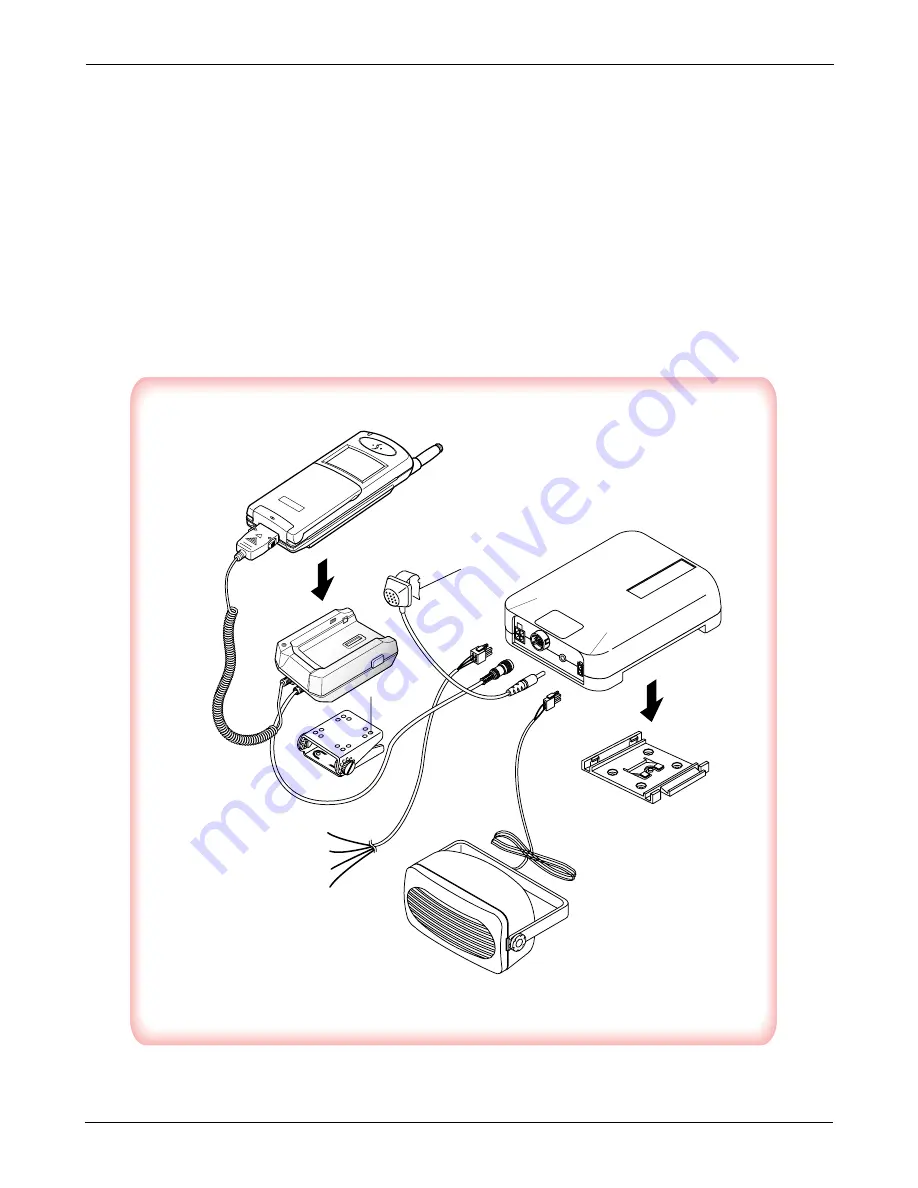
3-3-4 Cables
1. Connect the cradle and the hands-free box with the data cable. See the figure 3-4.
2. Connect the antenna cable to the RF jack of the cradle.
3. Connect the power cable as follows:
Connect the red wire to the battery (+) terminal, black wire to the vehicle chassis. Then connect the battery (-)
terminal to the vehicle chassis. Connect the yellow wire to the switched side of the ignition switch, and then
connect the white to the stereo mute wire from your vehicle stereo.
4. Connect the other end of the power cable to the PWR jack of the hands-free box.
Notes:
It is recommended to connect the power cable directly to the battery to avoid power noise.
Make sure the connection, in the vehicle, between the battery (-) terminal and vehicle chassis is made correctly.
Make sure the fuse having a proper capacity is used on the power cable.
Make sure the cables do not pass over any sharp metal edge that may damage it.
Summary of Contents for SCH 620
Page 75: ...9 Block Diagrams SAMSUNG Proprietary Contents may change without notice 9 1 9 1 Main Diagram ...
Page 77: ...SAMSUNG Proprietary Contents may change without notice 9 3 MEMO MEMO ...
Page 79: ...PCB diagrams Samsung Electronics 10 2 10 2 Main PCB Bottom Diagram ...
Page 80: ...PCB diagrams Samsung Electronics 10 3 10 3 CLC PCB Top Diagram 10 4 CLC PCB Bottom Diagram ...
Page 81: ...PCB diagrams Samsung Electronics 10 4 10 5 Hands free Kit PCB Top Diagram ...
Page 84: ...Samsung Electronics 11 3 Circuit diagrams 11 3 CLC Circuit Diagram ...
Page 85: ... Samsung Electronics Co Ltd APRIL 2000 Printed in Korea Code No GH68 00669A BASIC ELECTRONICS ...


