


TROUBLE SHOOTING
●
When the display is converted to Option Setting mode, the entire display is to be turned off except the
Fridge & Freezer 7-SEG LEDs as follows.
1) The following shows the way to shift the Freezer temperature by -3 (-6 ) This function is to shift its
base temperature. For example, if the current base temperature is -18 (0 ) and it is lowered by
3 (6 ) with the Option Setting function, the unit is to be controlled based on -21 (-6 ) that is
even though it shows -18 (0 ) on the display panel after shifting the base temperature.
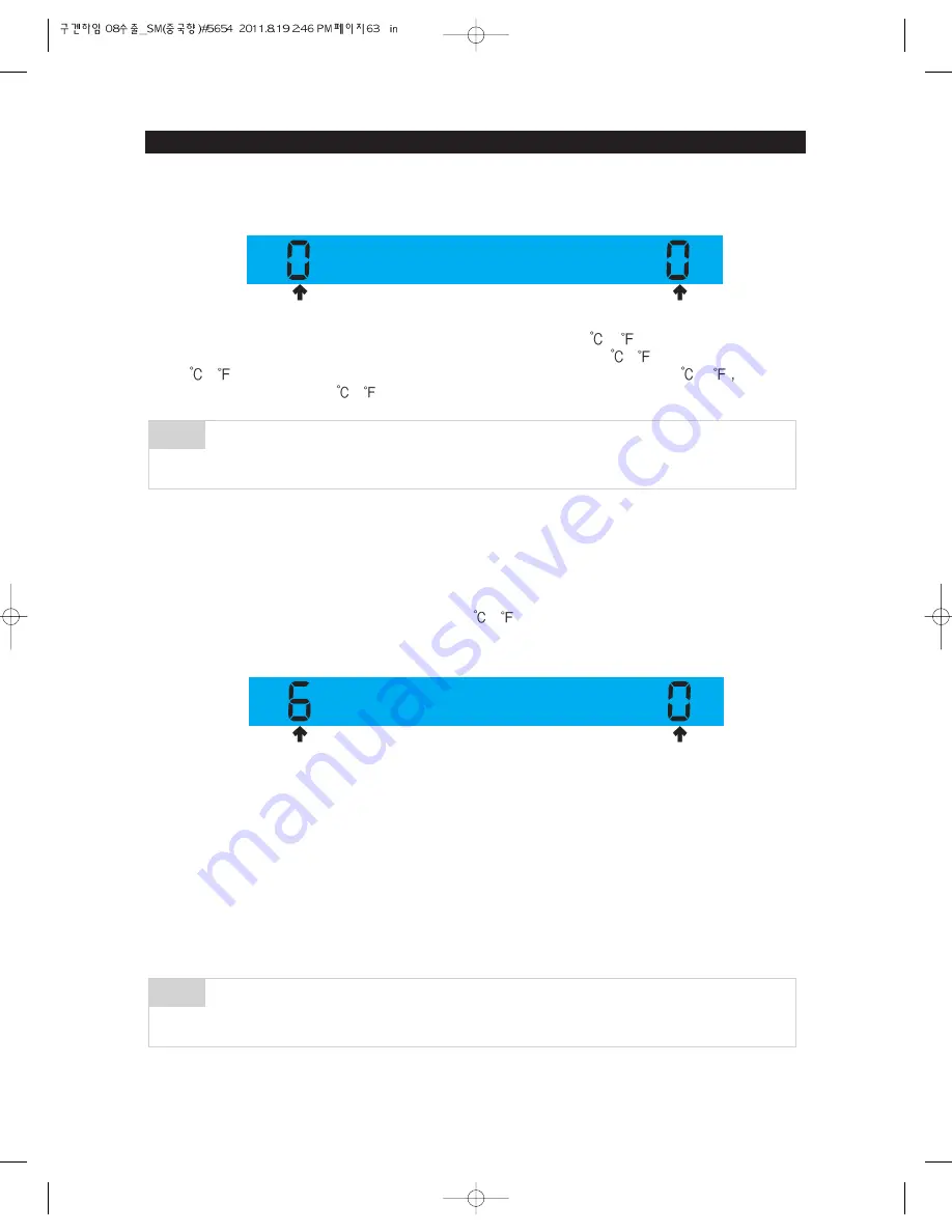
2) With the Option Setting mode, "0" blinks on both of the Fridge and the Freezer sections. (Generally,
they are set to "0" at both the Fridge and the Freezer sections. But, they can be changed for the
purpose of quality improvement.) - When "0" blinks on the Fridge section, it is set to the Freezer
Option Setting and the Freezer temp code will be displayed on the Freezer temp section.
3) If the Freezer temp code is set to "6" as the following table after setting the Fridge section to "0", the
Freezer base temperature is to be lowered by 3 (6 ) (Refer to the Freezer temperature setting
image.)
: In 15 seconds(20 seconds for RSG5B* Model) after completing the adjustment, MICOM is to store
the setting value in EEPROM and it goes back to the normal display mode, deactivating the Option
Setting mode.
4) The above Option Setting is the same for both of the Dispenser model and the No-Dispenser model.
5) With the same method as the above, you can control the Fridge and the Cool Select Zone
temperature.
6) Make sure not to change the factory-set default values otherwise exception cases. Also, the Option
Setting is to be completed when it goes back to the normal display mode in 20 seconds. So, do not
turn off the unit before it goes back to the normal display mode.
The units are shipped out with all their data being cleared. i.e. the setting values are "0" for all
together. But, for the purpose of quality improvement, the settings can be changed before
being shipped out, make sure to check relevant SVC bulletins.
NOTE
There are more functions which can be adjusted. But, they are not to be described in this
manual because they are not actually related to the diagnosis of the unit. (Do not change the
option settings other than the ones described in this manual)
NOTE
Option Value
Option Item
Option Code
Option Item
63
Summary of Contents for RSG5D series
Page 2: ......
Page 11: ...11 PRODUCT SPECIFICATIONS Comparison with competitor...
Page 12: ...2 3 1 Basic Specification PRODUCT SPECIFICATIONS 2 3 2 Electric Parts Specification 12...
Page 13: ...PRODUCT SPECIFICATIONS 13 AC 250V 3A AC 125V 6A AC 125V 6A AC 250V 3A...
Page 72: ...TROUBLE SHOOTING SPM FREEWHEELING DIODE Voltage 72...
Page 90: ...90 PCB DIAGRAM 5 3 Connector Arrangement Description Main Board...
Page 91: ...91 PCB DIAGRAM 5 4 LED blinking frequency depending on protecting functions...
Page 92: ...92 6 WIRING DIAGRAM 6 1 RSG5D F K 220 240V...
Page 93: ...93 93 WIRING DIAGRAM 6 2 RSG5D F K 220 240V...
Page 94: ...94 WIRING DIAGRAM 6 3 RSG5K F D 110 127V...
Page 95: ...95 WIRING DIAGRAM 6 4 RSG257...
Page 96: ...96 WIRING DIAGRAM 6 5 RSG5B V...
Page 97: ...97 97 7 SCHEMATIC DIAGRAM BLOCK DIAGRAM 7 1 Main PCB Schematic Diagram...
Page 98: ...98 98 98 SCHEMATIC DIAGRAM BLOCK DIAGRAM 7 2 Main PCB Schematic Diagram...
Page 99: ...99 99 SCHEMATIC DIAGRAM BLOCK DIAGRAM 7 2 1 BLOCK DIAGRAM RSG5F D...
Page 100: ...100 100 100 SCHEMATIC DIAGRAM BLOCK DIAGRAM 7 2 2 BLOCK DIAGRAM RSG5K...
Page 101: ...101 101 101 SCHEMATIC DIAGRAM BLOCK DIAGRAM 7 2 3 BLOCK DIAGRAM RSG257...
Page 102: ...102 102 102 SCHEMATIC DIAGRAM BLOCK DIAGRAM 7 2 4 BLOCK DIAGRAM RSG5B V...
Page 103: ...103 103 103 SCHEMATIC DIAGRAM BLOCK DIAGRAM 7 2 5 BLOCK DIAGRAM RSG257...
Page 104: ...104 104 104 SCHEMATIC DIAGRAM BLOCK DIAGRAM 7 2 6 BLOCK DIAGRAM RSG257...
Page 105: ...105 105 105 SCHEMATIC DIAGRAM BLOCK DIAGRAM 7 2 7 BLOCK DIAGRAM Inverter PBA...
Page 106: ...106 8 REFERENCE INFORMATION 8 1 RSG5...


