background image

48

TROUBLESHOOTING

4-1. Function for failure diagnosis

4-1-1. Test mode (manual operation / manual defrost function)

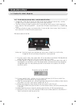
•  If Freezer Key + Alarm Key on the front of panel are pressed simultaneously for 8 seconds , it will be 

changed to the test mode and all displays on the front of panel will be off.

•  If any key on the front of panel is pressed within 15 seconds after the test mode, it will be operated as 

below sequence : Manual operation(FF) -> manual defrost of freezer compartments(Fd) -> cancel(Display 
all off)

•  If any key on the front of panel is not pressed within 15 seconds after the test mode, the test mode will 

be canceled and it will be returned to previous mode.

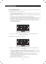
Freezer Key + Alarm Key are pressed simultaneously for 8 seconds, (displays are all off) It will be 

changed to the test mode (manual operation) by pressing any key.

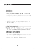
1-1)  If any key is pressed once in test mode, blinks "FF" on the display and it indicates the refrigerator has 

entered the manual operation. At this moment, buzzer beeps as an alarm.

1-2)  If manual operation is selected, compressor will run at once without 7 minutes delay in any mode. If 

the refrigerator is on the defrost cycle at the moment, defrost will be finished and manual operation 
will begin.(Be careful if manual operation get started at the moment of compressor off, over load 
could be occurred)

1-3)  If manual operation works, compressor & f-fan operate continuously for 24 hours and fresh food 

compartment will be controlled by the setting temperature.

1-4)  When the manual operation runs, setting temperature will be selected automatically as below: freezer 

compartment -8°F(-23°C), fresh food compartment 34°F(1°C).

1-5)  During manual operation, Power Freeze & Power Cool function will not be work. 

If a function is selected, the power function icon of the selected function will be off automatically after 
10 seconds.

1-6) Manual operation can be canceled by removing power from the unit, then resupplying power.
1-7)  Alarm(0.25 sec ON/ 0.75 sec OFF) will beep continuously until manual operation is completed and 

there is no function to make the sound stop.

1) Manual operation function

Compulsion working : 3600RPM

Summary of Contents for RH29H9000SR

Page 1: ...H22H9010SR AA RH29H9000SR AA REFRIGERATOR REFRIGERATOR CONTENTS 1 PRECAUTIONS SAFETY WARNINGS 5 2 PRODUCT SPECIFICATIONS 8 3 DISASSEMBLY AND REASSEMBLY 19 4 TROUBLESHOOTING 47 5 PCB DIAGRAM 75 6 WIRIN...

Page 2: ...pliance may result in personal injury and property damage The manufacturer or dealer cannot be responsible for the interpretation of this information SAMSUNG ELECTRONICS AMERICA INC Technical Service...

Page 3: ...p Disassembling Freezing Compartment 31 3 13 Assembly Hinge Up Disassembling Show Case of Cold Compartment 32 3 14 Assembly Hinge Up Disassembling Cold Compartment 33 3 15 Assembly Locker Disassemblin...

Page 4: ...78 5 4 Connector Layout with part position Inverter Board 79 6 Wiring Diagram 80 6 1 Model RH22 RH29 80 7 Block Diagram 81 7 1 Whole block diagram 81 7 2 Inverter Block Diagram 82 8 Model code table...

Page 5: ...embled state of parts It should be the same as the previous state O Check out the surrounding conditions Change the location if the fridge is located at humid wet places or the installed state is unst...

Page 6: ...components on the replacement Check the correct model rated voltage rated current operating temperature and so on On repair make sure that the wires such as harness are bundled tightly Bundle tightly...

Page 7: ...cause things to fall down with may inflict a wound Prohibited Warning Caution Do not allow users to disassemble repair or alter It may cause fire or abnormal operation which leads to injury Do not di...

Page 8: ...unction 9 2 2 Model Speci cation 10 2 3 Basic Speci cation 11 2 3 1 Electric Parts Speci cation 12 2 3 2 Electric Component 13 2 4 Model Inform For E Cost Model Code introduction application date Weig...

Page 9: ...glass also lets you check on the amount of ice available at a glance Surround Multi Air Outlets Cooling air ows out through multiple outlets in every shelf level This provides even cooling throughout...

Page 10: ...es that all the shelf space can be fully utilized Ice cubes are quickly produced and the clear ice bucket lets you easily see the amount of ice cubes produced Premium Design Ice Water Dispenser Quick...

Page 11: ...1 4 x 69 6 8 912 x 896 x 1774 35 7 8 x 35 2 8 x 69 6 8 Dimensions of package width x depth x height 972 x 820 x 1909 38 2 8 x 32 2 8 x 75 1 8 972 x 995 x 1909 38 2 8 x 39 1 8 x 75 1 8 Rated frequency...

Page 12: ...zer Component ON THERMISTOR F SENSOR 502AT Strong C 20 5 20 5 Intermediate C 18 18 Weak C 16 16 Cold compartment ON THERMISTOR R SENSOR 502AT Strong C 1 1 Intermediate C 3 3 Weak C 6 6 Components for...

Page 13: ...defrosting heater in freezing compartment Thermostat BT 121 M On 40 C Off 60 C Bimetal for preventing overheating of defrosting heater in cold compartment Noise lter 5 0 at 25 OLP Type 4TM445PHBYY 82...

Page 14: ...artment Thermostat BT 121 M On 40 C Off 60 C Bimetal for preventing overheating of defrosting heater in cold compartment Noise lter 5 0 at 25 OLP Type 4TM445PHBYY 82 4TM445PHBYY 82 4TM445PHBYY 82 4TM4...

Page 15: ...el Code introduction application date Weight Inform NO Model Code introduction application date Weight NET GROSS 1 RH29H9000SR AA 08 06 2015 158 170 2 RH22H9010SR AA 08 06 2015 154 165 3 RH29H9000SR A...

Page 16: ...16 PRODUCT SPECIFICATIONS 2 5 Dimensions mm inch 46 1170mm MODEL RH22H90...

Page 17: ...17 PRODUCT SPECIFICATIONS 52 7 8 1345mm 0 160 0 160 MODEL RH29H90...

Page 18: ...18 PRODUCT SPECIFICATIONS 2 6 Optional Material Speci cation Photograph Part Name Part Code Quantity Remark FILTER WATER DA29 00019A 1 ALL MODEL ASSY PACKING DA90 08491A 1...

Page 19: ...sembling Show Case of Cold Compartment 32 3 14 Assembly Hinge Up Disassembling Cold Compartment 33 3 15 Assembly Locker Disassembling Cold Compartment 34 3 16 Evaporator 36 3 17 Main PCB and Inverter...

Page 20: ...ator in a damp place or place where it may come in contact with water Deteriorated insulation of electrical parts may cause an electric shock or re In order to reduce the risk of electric shock the ap...

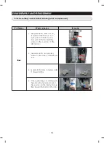
Page 21: ...SEMBLY 3 2 Interior Fridge Part Name Description Figure Shelf Pull the Shelf out to the front Drawer cover Remove all Drawers before disassembling the cover Pull the cover out to the front Pull the ip...

Page 22: ...age the Evaporator Cover pull the Multi duct Fridge in the direction of the front Disengage the housing connector Assembly will progress in reverse of disengage and assemble the GROMMENT and MULTI 2ea...

Page 23: ...count clockwise Refer to the picture Remove the water lter by pulling it Refer to the picture Push the water lter directly Turn the water lter clockwise until it locked CAUTION Be sure to ush the disp...

Page 24: ...assembling the Case Water Filter take out water lter and drawers and shelves located on the Case Water Filter Remove screws While pushing the Tube Fitting remove the 2 Water Tube Turn the refrgerator...

Page 25: ...D REASSEMBLY 3 6 Cover Display Water Dispenser Part Name Description Figure Cover Display Remove a screw under the display cover Remove the display cover by pulilng it up Disengage the housing connect...

Page 26: ...Case Ice Route Assy Assembly shall be in order from the disassembly Case Ice and Route shall be assembled inside of hose Otherwise assemble cannot be accomplished When assembling Cover Display rst ins...

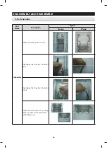
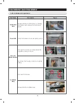
Page 27: ...ASSEMBLY AND REASSEMBLY 3 8 Interior Freezer Part Name Description Figure Shelf Pull the Shelf out to the front Drawer Cover Remove all Drawers before disassembling the cover Pull the cover out to the...

Page 28: ...Y AND REASSEMBLY 3 9 Evaporator Cover Freezer Part Name Description Figure Evap Cover Freezer Remove the Cap Screw Remove the 4 screws by turning counterclockwise Pull the Evap Cover in the direction...

Page 29: ...isassemble the Electrically driven DAMPER after disassemble the INSULATION DUCT REF UP 3 Remove the two COVER SCREW which is on the center of freezer by driver 4 Remove the four SCREW of COVER EVA FRE...

Page 30: ...30 DISASSEMBLY AND REASSEMBLY 3 11 Deodorizer Part Name Description Figure Cover Deodorizer 1 Remove the Cover Deodorizer using at head driver 2 Replace Catalyst 3 Reassemble in the reverse order...

Page 31: ...er cord and Remove 3 cover screws using a Phillips screwdriver Then open the refrigerator door and pull the hooks on the sides to loosen the cover Lift up the cover and towards you to detach it 2 Disa...

Page 32: ...ord and Remove 3 cover screws using a Phillips screwdriver Then open the refrigerator door and pull the hooks on the sides to loosen the cover Lift up the cover and towards you to detach it 2 Disassem...

Page 33: ...ve 3 cover screws using a Phillips screwdriver Then open the refrigerator door and pull the hooks on the sides to loosen the cover Lift up the cover and towards you to detach it 2 Disassemble two conn...

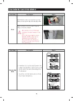
Page 34: ...d lay the door on the oor and disassemble the two fastening screws on the cover lock of the internal door 2 Disassemble the two fastening screws on the locker of the external door 3 Assemble the doors...

Page 35: ...in upper direction until the water hose is eliminated from lower hinge Do not pull the door forward to remove it It cause injury of water hose and tubing Part Name Description Figure Reassembly doors...

Page 36: ...Part Name Description Figure Freezer Fridge Evaporator Remove the Evaporator cover Disengage the housing connector left Disengage the housing connector right Remove the evaporator by pulling the lowe...

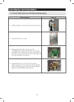
Page 37: ...he thirteen connectors of the housing Number of the housing connectors may vary dependent upon models and functions While pressing the upper hook on the location shown on the gure pull the main main P...

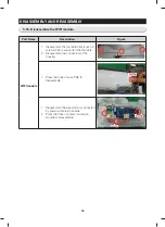
Page 38: ...e 1 Disassemble the top table after loosen 3 screw which is supported the top table 2 Disassemble two connectors of the housing 1 Press the hook of case PBA to disassemble 0 1 Disassemble the wire whi...

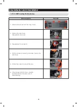
Page 39: ...screws from the Comp Cover 2 Remove the drain hose Disassemble one screw 3 Disassemble the connector 4 Pull the connector forward and incline it toward the drain hose 5 Rotate the connector around the...

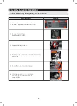
Page 40: ...emove ve screws from the Comp Cover 2 Remove the drain hose Disassemble one screw 3 Disassemble the connector 4 Pull the connector forward and incline it toward the drain hose 5 Rotate the connector a...

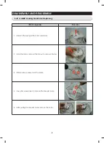
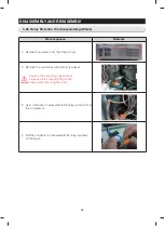
Page 41: ...acing Work sequence Remarks 1 Remove the spring with a at screwdriver 2 Hold the motor and pull the fan out to remove the fan 3 Remove two screws from the motor 4 Use a at screwdriver to remove the br...

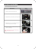
Page 42: ...rom the Comp Cover 2 Remove the cover relay with a at screwdriver CAUTION Caution Pipe bending or exercise of excessive force may pinching on the hands when removing the cover 3 User a at driver to di...

Page 43: ...p Cover 2 Disassemble the housing connector from the step valve 3 Disassemble one screw and pull the step valve up to remove the valve as shown on the gure 4 Remove the refrigerant and disassemble the...

Page 44: ...sy by holding the handles and pulling up the bottom part slightly Cover I M Lift up the Icemaker Cover and gently pull out Assy Ice Maker Indoor Unscrew the 4 screws and disassemble the Auger Motor As...

Page 45: ...AND REASSEMBLY Part Name Description Figure Auger Motor 1 Pull the shelf out to the front side 2 Unscrew 4 screws by turning counter clockwise 3 Disconnect the housing connector by pulling as shown 3...

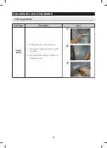
Page 46: ...e one set screw counterclockwise with a hexagonal wrench to remove it from the bottom of the handle 2 Pull the bottom of the handle to remove it 3 Slide the entire handle downward to disassemble it Pa...

Page 47: ...47 4 TROUBLESHOOTING 4 1 Function for failure diagnosis 48 4 2 Diagnostic method according to the trouble symptom Flow Chart 62...

Page 48: ...his moment buzzer beeps as an alarm 1 2 If manual operation is selected compressor will run at once without 7 minutes delay in any mode If the refrigerator is on the defrost cycle at the moment defros...

Page 49: ...eezer compartment will be canceled and the unit will return to the normal operation Or all test functions will be canceled by turning main power ON and OFF 3 Test cancel mode 1 1 If there is no answer...

Page 50: ...turn to normal display mode 2 1 If Freezer Key Fridge Key are pressed simultaneously for 6 seconds during normal operation the temperature setting display will operate for 2 seconds ON OFF 0 5sec each...

Page 51: ...cable fan motor Feed back signal line contact error motor wire separation motor error The voltage of MAIN PCB CN74 2PIN 1PIN shall be between 7V 12V F DEF Error Separation of freezer compartment defro...

Page 52: ...nks Check if door has been open for a long time or if hot food has been stored in the compartment If the reason for the error is removed the error code disappears after a pre determined period of time...

Page 53: ...om signal is outputting However It means that micom signal is outputting it does not mean whether load is operating or not That is to say that though load operation is displayed load could not be oper...

Page 54: ...applicable LED blinks F 1 F FAN Low When FZ compartment FAN operates with low speed applicable LED blinks F 1 F DEF Heater When FZ compartment defrost heater operates LED blinks F 1 C FAN High When c...

Page 55: ...ion contents of Cooling Off mode Display Fan motor and etc operate normally not to operate compressor and Door Open Alarm Defrost is not operated including french heater Display function of the initia...

Page 56: ...food and freezer compartments case will be explained only because all options are operated with the same method according to the option table If Lighting Key Fridge Key are pressed simultaneously for...

Page 57: ...perature of freezer compartment will be lower than 4 2 0 C Refer to the picture changing the freezer compartment temperature 4 Option changing method as above is the same as all RH22 RH29 model 5 By t...

Page 58: ...Temp compensation 0 0 F 0 0 C 1 1 F 0 5 C 2 2 F 1 0 C 3 3 F 1 5 C 4 4 F 2 0 C 5 5 F 2 5 C 6 6 F 3 0 C 7 7 F 3 5 C 8 1 F 0 5 C 9 2 F 1 0 C 10 3 F 1 5 C 11 4 F 2 0 C 12 5 F 2 5 C 13 6 F 3 0 C 14 7 F 3...

Page 59: ...2 45min 3 53min 4 55min 5 57min 6 65min 7 70min 8 50min Setting value FZ compartment Code Water Settings 0 94cc 1 104cc Setting value FZ compartment Code Temp compensation 0 7 5 C 1 7 0 C 2 6 5 C 3 8...

Page 60: ...g value FZ compartment Code Temp Display Option 0 Normal Display Temp display temporally on at use 1 Always Temp Display On 2 Always Temp Display On Setting value FZ compartment Code Comp RPM 0 No RPM...

Page 61: ...rate changing table of dispenser heater ex If you want to change the dispenser heater operation rate to 20 Setting value FZ compartment Code Rate change 0 0 0 1 20 operation up to 100 Set item Dispens...

Page 62: ...42 8 44 6 46 4 48 2 50 51 8 53 6 55 4 57 2 59 60 8 62 6 64 4 66 2 68 69 8 71 6 73 4 75 2 77 78 8 80 6 82 4 84 2 86 87 8 89 6 91 4 93 2 95 96 8 98 6 100 4 102 2 3 107 3 057 3 006 2 955 2 904 2 853 2 80...

Page 63: ...3152 3179 3206 3233 3260 3288 3316 3344 3372 3400 3426 3452 3478 3504 3530 3566 3595 3624 3653 3683 186 193 200 207 213 220 227 233 240 247 253 259 265 272 278 284 291 297 303 309 315 321 327 333 339...

Page 64: ...of power cable assembling 2 Panel PCB replacing No Yes Yes Yes Start AC input power and high voltage of DC 310V or higher are generated at SMPS PCB and INVERTER PCB power terminal Be cautious during...

Page 65: ...SENSOR 2PIN 3PIN F SENSOR 2PIN 4PIN F DEF SENSOR 2PIN 5PIN R SENSOR 2PIN 6PIN R DEF SENSOR 2PIN 9PIN CV SENSOR 2PIN 10PIN CV DEF SENSOR 2PIN 11PIN HUM1 SENSOR 2PIN 12PIN HUM2 SENSOR 2PIN 13PIN ICEROOM...

Page 66: ...the resistance between CN30 1 and 2 PBA Thermistor are ok Check the contact of the connector again Refer to Circuit Diagram and Temp Sensor Troubleshooting in this manual Refer to Circuit Diagram and...

Page 67: ...d YES Repair the defective contact of the connector or insert the connector properly NO The connector CN50 is Inserted properly YES Replace REED S W NO Door S W is good MAIN PBA DOOR S W are good Sepa...

Page 68: ...nable to hear in case there is heavy noise or built in environment 3 If a buzzer does not sound Start Check Replace a buzzer on Panel PBA NO YES DingDond Sounds when a button on the display panel is p...

Page 69: ...ve contact NO DOOR PANEL PBA Connector is inserted properly NO Defective PANEL PBA YES It lights up after PANEL PBA replacement Check F R Door Wiring Short or Open Wire Check F R CABI Wiring Short or...

Page 70: ...gnal If Micom senses no signal Micom make Fan Motor stop for 10 sec and try to operate it again Micom keeps doing the same procedure 4 times until Micom receive the signal If it still fails MICOM stop...

Page 71: ...lamp control on PBA is normal 1 Turn off the power for repair because there is risk of electric shock when replacing the internal lamp 2 Please keep in mind you could get burnt by the excessive heatin...

Page 72: ...Is the output voltage of main power conversion board as 5V correctly Is the six pins connector connected to main power conversion board correctly Is the cable connected to main board CN03 correctly A...

Page 73: ...ing again Select the wrong wireless router Select the wireless router which is connected with Smart mobile Password is wrong Enter the password correctly E Smart LED ON Select the wrong wireless route...

Page 74: ...tween COMP U V and W Phase CN102 2 Short among IPM Pins No 1 26 3 Drop the IPM operating Voltage under DC 13 5V 4 Other cases check the COMP cycle etc IPM Fault Abnormal Current Detection 1 Open the C...

Page 75: ...DIAGRAM 5 1 PBA Layout with part position 76 5 2 PBA Layout with part position Inverter Board 77 5 3 Connector Layout with part position Main Board 78 5 4 Connector Layout with part position Inverter...

Page 76: ...Ice maker kit control D Damper Damper heater control E dispenser controlling part F Panel PBA communication and power supply circuit G Defrost Heater controlling part H Inverter Comp driving signal se...

Page 77: ...r circuit for the Compressor control 2 COMP Driving Feedback Circuit It receives the COMP operation signals from the Main PBA and feedbacks the inverter errors to the Main PBA 3 Micom MN103SFC2D 4 BOO...

Page 78: ...78 PCB DIAGRAM This document can not be used without Samsung s authorization 5 3 Connector Layout with part position Main Board...

Page 79: ...79 PCB DIAGRAM This document can not be used without Samsung s authorization 5 4 Connector Layout with part position Inverter Board AC 115V COMP 1 DC 5V 2 GND 3 COMP RPM 4 COMP Feedback...

Page 80: ...80 6 Wiring Diagram 6 1 Model RH22 RH29 This document can not be used without Samsung s authorization...

Page 81: ...81 7 Block Diagram 7 1 Whole block diagram This document can not be used without Samsung s authorization...

Page 82: ...82 BLOCK DIAGRAM This document can not be used without Samsung s authorization 7 2 Inverter Block Diagram...

Page 83: ...83 8 Model code table 8 1 MODEL RH22 This document can not be used without Samsung s authorization...

Page 84: ...84 MODEL CODE TABLE 8 2 MODEL RH29...

Page 85: ...85 MODEL CODE TABLE 8 2 MODEL E COST...

Page 86: ...ision 2018 Printed in Korea This Service Manual is a property of Samsung Electronics Co Ltd Any unauthorized use of Manual can be punished underapplicable International ordomestic law Europe CIS Midea...

Reviews: