98
Pcb diagram
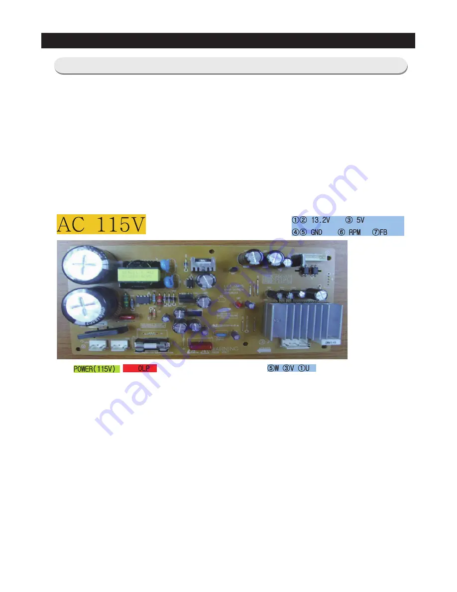
5-4) Connector Layout with part position (Inverter Board)
This document can not be used without Samsung's authorization
Page 1: ...OR REFRIGERATOR CONTENTS 1 Precautions safety warnings 4 2 Product specifications 8 3 Disassembly and Reassembly 25 4 Troubleshooting 50 5 Pcb Diagram 94 6 Wiring Diagram 99 7 Schematic Diagram 100 MODEL NAME RF263TEAE RF263BEAE ...
Page 2: ... may result in personal injury and property damage The manufacturer or dealer cannot be responsible for the interpretation of this information SAMSUNG ELECTRONICS AMERICA INC Technical Service Guide Copyright 2012 All rights reserved This service guide may not be reproduced in whole or in part in any form without written permission from the SAMSUNG ELECTRONICS Company WARNING ...
Page 3: ...rator Door 27 3 3 Door Handle Refrigerator 29 3 4 Door Handle Freezer 29 3 5 Refrigerator Light 30 3 6 Cover Display Water Dispenser 30 3 7 Water Dispenser 31 3 8 Glass Shelf 32 3 9 Foldable Glass Shelf 32 3 10 Vegetable Fruit Drawers Shelf 33 3 11 Case Water Filter 34 3 12 Cool Select Pantry 35 3 13 Motor Damper 35 3 14 Water Filter Assembly Disassembly 36 3 15 Gallon Door Bin 37 3 16 Vertical Hi...
Page 4: ...er COMP 81 4 2 9 When alarm sounds continuously without stop related with buzzer sound 82 4 2 10 When the Panel PCB does not operate normally 84 4 2 11 If Pantry Panel PCB is not working normally 85 4 2 12 When refrigerator ROOM Lamp does not light up 86 4 2 13 If ICE Water is not supplied 87 4 2 14 If Cubed or Crushed Ice is not supplied 89 4 2 15 If Cover Ice Route Motor Geared Motor is not work...
Page 5: ...heck the location where the refrigerator will be used If the refrigerator will be used in a damp or wet space or if installation will be unstable the unit should be relocated The refrigerator must be grounded properly An earth ground should be used if there is a risk of high humidity or wetness The refrigerator should be plugged into a dedicated outlet Make sure the power cord is not damaged crush...
Page 6: ...It may cause electric shock Warning Warning Caution Caution Unplug Use the rated components on the replacement Check the correct model rated voltage rated current operating temperature and so on On repair make sure that the all wiring harnesses are reconnected Wiring harnesses should be connected tightly and kept dry Bundle tightly wires in order not to be detached by the external force and then n...
Page 7: ... things to fall down which may cause injury Prohibited Warning Caution Consumers must not try to repair the refrigerator Electrical and mechanical parts could injure the consumer Do not disassemble The refrigerator should be plugged into a dedicated outlet Multiple plugs in the outlet could cause excessive heat or fire Prohibited Make sure the power cord is not damaged or crushed A damaged cord co...
Page 8: ...e rest of the flooring This surface should be strong enough to support a fully loaded refrigerator or approximately 660lbs 299kg FLOORING Protect the finish of the flooring Cut a large section of the cardboard carton and place under the refrigerator where you are working When moving be sure to pull the unit straight out and push back in straight MOVING ...
Page 9: ...pecification Specification Chart 13 2 5 Dimensions of Refrigerator Inches 16 2 6 Optional Material Specification 17 2 7 Refrigerant Route in Refrigeration cycle 18 2 7 1 Principle of freezeer 19 2 7 2 Operation theory of refrigeration cycle components 20 2 7 3 Refrigeration Cycle Type 23 2 8 Cooling Air Circulation 24 ...
Page 10: ...e therefore more efficient Food odor from the refrigerator does not affect food in the freezer due to separate air flow circulation One Lever Dispenser One lever dispenser easily switches between ice and water Secure Auto Close Door System Doors close tightly Food on the doors stays cool Prevents moisture from forming on the outside of the doors Easy Handle System Ez open Freezer Door Ergonomic Do...
Page 11: ...ifications Slim Water Filtration System Slim water filter is placed between crispers for without removing items from Refrigerator Dual Ice Maker 10 cubes ice Maker Refrigerator 7 cubes ice Maker Freezer FOR RF263TEAE ...
Page 12: ...frigerant Charge R134a 5 64 oz 160g Compressor MKV190C L2J 1314 Btu hr 0 385kw Compressor oil Freol 5 15c R Capillary tube Dia Length 0 032 118 0 82mm 3500mm Clearance must be provided for air circulation AT TOP 1 25mm AT SIDES 1 25mm AT REAR 2 50mm Fan Fan Fan Fan Air inlet Air inlet Air inlet Air inlet Heat exchanger Heat exchanger Fan Fan Air inlet Air inlet Heat exchanger ELECTRICAL SPECIFICAT...
Page 13: ...12 product specifications 2 3 Interior Views ...
Page 14: ...al 25 6 725 2ℓ 25 6 725 2ℓ Freezer 7 9 222 6ℓ 7 9 222 6ℓ Refrigerator 17 7 502 6ℓ 17 7 502 6ℓ Efficiency of Volume 53 36 53 36 Weight Set 140kg 140kg Packing 152kg 152kg Packing Width 38 5 8 Inch 980mm 38 5 8 Inch 980mm Depth 36 2 8 Inch 920mm 36 2 8 Inch 920mm Height 75 6 8 Inch 1925mm 75 6 8 Inch 1925mm Compressor RECIPROCATE RECIPROCATE Rated Frequency and Frequency AC 115V 60Hz AC 115V 60Hz Re...
Page 15: ... 2 F 17 C Refrigerator Model Temperature Selection On F Off F THERMISTOR R SENSOR 502AT 34 F 1 C 36 F 2 C 32 F 0 C 37 F 3 C 39 F 4 C 35 F 2 C 44 F 7 C 46 F 8 C 42 F 6 C Defrost Related Components Defrost Cycle First Defrost Cycle Concurrent defrost of F and R 6hr 10min Defrost Cycle FRE 12 30hr vary according to the conditions used Defrost Cycle REF 6 15hr vary according to the conditions used Pau...
Page 16: ...ter Drain Heater REF DC12V 2 3W Over Load Relay Model 4TM445PHBYY 82 Temp ON 156 2 16 2 F 69 9 C Temp OFF 257 9 F 125 5 C Rated Voltage AC 115V 60Hz Motor BLDC FRE DC 12V 0 17A DREP5020LC Motor BLDC BOX FAN REF DV 12V 0 16A 3612JL 04W S49 G51 Motor BLDC BOX FAN ICE ROOM DC 12V 0 1A 2606JL 04W S39 UQ1 Motor BLDC CIRCUIT DC 12V 0 22A DRCP5030LA Lamp LED FRE DC 12V 85 130mA Lamp LED REF DC 12V 510 78...
Page 17: ...29 1 4 745mm 3 3 8 86mm 21 1 2 545mm 41 3 4 1060mm 5 8 15mm 70 1778mm 1 1 4 32mm 2 8 5mm 33 2 8 842mm 35 5 8 905mm 35 6 8 908mm 24 1 4 618mm 3 1 4 85mm 52 1 8 1324mm 18 11 16 475mm 48 1220mm 2 5 Dimensions of Refrigerator Inches ...
Page 18: ...tions 2 6 Optional Material Specification Part Name Part Code AMOUNT FILTER WATER ASSY DA29 00020B 1 ASSY PACKING SUB DA99 00240S 1 LED LAMP REF DA41 00676G 4 LED LAMP CASE VEG R L DA41 00519S 1 LED LAMP FRE DA41 00676G 1 ...
Page 19: ...18 product specifications Compressor Conden Hot Pipe Dryer Capillary Tube Refrigerator Evaporator Pipe Direct Ice Freezer Evaporator Suction Pipe Compressor 2 7 Refrigerant Route in Refrigeration cycle ...
Page 20: ...19 product specifications 2 7 1 Principle of freezeer ...
Page 21: ...ter at the lower part of product and radiate heat manually by fan Radiate condensed potential heat up to liquefy completely and make change the state without changing the gas temperature itself Pipe thickness Low pressure 6 3mm High pressure 4 7mm Capillary About 0 4 0 8mm Condenser length Based on 300ℓ 26 5 M Assistance 5 M HOT PIPE 6 6 M CLUSTER PIPE 4 17 M Capillary 1 Role A device which makes ...
Page 22: ...ant gas flowed out from evaporator and make high temperature and pressure refrigerant liquid in the compressor and send it to the condenser 2 Type of Condenser a Back and forth motion type A method that pistol makes back and forth motion through shaft and cylinder of motor rotation and compresses Used for household refrigerant b Rotary Type A method that inhales the refrigerant gas through the gap...
Page 23: ...hetic insulating material insulator Influence of foreign substance Increase of condensed temperature Increase of temperature Decrease of cooling efficiency Shorten the life by friction between oil and foreign substance in the compressor Accumulator 1 Role To send a pure refrigerant gas to compressor by removing completely the refrigerant liquid from evaporator If a refrigerant liquid go into the c...
Page 24: ...roduct specifications HM Cycle Compressor Condenser Hot Pipe Back Cluster Pipe Refrigerator Evaporator Dryer Capillary Tube Compressor Freezer Evaporator ICE Pipe Suction Pipe 2 7 3 Refrigeration Cycle Type ...
Page 25: ...Air Circulation Refrigerator Freezer In some cases frost blocks the return hole in freezer and it may cause weak cooling or No ice making Ice Maker Duct in Fridge Discharge Return Duct Duct in Freezer Discharge Return Duct Discharge Return ...
Page 26: ...f 33 3 11 Case Water Filter 34 3 12 Cool Select Pantry 35 3 13 Motor Damper 35 3 14 Water Filter Assembly Disassembly 36 3 15 Gallon Door Bin 37 3 16 Vertical Hinged Section 37 3 17 Evaporator Cover In Refrigerator 38 3 18 Evaporator In Refrigerator 39 3 19 Freezer Door 40 3 20 Ice Maker 41 3 21 Auger Motor Fan 43 3 22 Freezer Light 44 3 23 Door Switch In Freezer 44 3 24 Evaporator Cover In Freeze...
Page 27: ...les or glass containers in the freezer When the contents freeze the glass may break and cause personal injury Do not store volatile or flammable substances in the refrigerator The storage of benzene thinner alcohol ether LP gas and other such products may cause explosions Water whitening phenomenon All water provided to refrigerators flows through the core filter which is an alkaline water filter ...
Page 28: ...eft door hinge To disconnect the connector more easily press the end of the hook and pull connector CAUTION Make sure unit is unplugged 3 As shown in the picture Remove water tube from hinge by holding at the both sides of the Tube Fitting and pulling it out And remove the Tube Fitting by pulling the water hose after pushing in the locking ring tab at the end of the Tube Fitting 4 After pulling th...
Page 29: ...he door straightly up to remove CAUTION Be careful not to drop the door 6 Lift the grommet hinge straightly up to remove 7 With a Philips head screwdriver remove the screw attatched to the lower left and right door hinges With a 0 4in Hex wrench remove the 2 flat head screws Remove the lower left and right door hinges ...
Page 30: ...dle about 0 1in by using Hex wrench 2 Pull the Set handle out by moving it straight up CAUTION Be careful not to scratch or break the parts Part Name How To Do Descriptive Picture Door Handle Freezer 1 Loosen the Set Screw situated at the bottom right of the appliance about 0 1in by using Hex wrench 2 Pull the Set handle out by moving it to the right side CAUTION Be careful not to scratch or break...
Page 31: ...ure Refrigerator Light 1 Press the tabs on the back of the Lamp Cover and take it off 2 Remove the 3 screws And separate the LED panel Part Name How To Do Descriptive Picture Cover Display 1 Remove a screw under the display cover 2 Remove the display cover by pulling it up 3 Disengage the housing connector of display cover ...
Page 32: ...ade screwdriver 2 Remove 2 screws of the Case Ice Route Assy 3 Pull the Case Ice Route Assy 4 Assembly shall be in order from the disassembly Case Ice and Route shall be assembled inside of hose Otherwise assemble cannot be accomplished 5 When assembling Cover Display first insert it from leftside and then assemble to rightside Otherwise the hook can be broken ...
Page 33: ...ldable Glass Shelf Part Name How To Do Descriptive Picture Glass Shelf Remove the shelf by lifting the front part of the shelf up and pulling it out Part Name How To Do Descriptive Picture Foldable Glass Shelf Remove 2 screws of the Folderble Glass Shelf ...
Page 34: ...o Do Descriptive Picture Vegetable Fruit Drawers Shelf 1 Remove the vegetable fruit drawer 2 Push the button on the left side of the shelf and lift up to release from the Assembly Refer to the picture 3 Remove the vegetable fruit drawer shelf by pulling it out Refer to the picture ...
Page 35: ...all drawers and shelves 1 a Remove Cover Tube Fitting 1 b Remove the Water tube blue from the tube fitting by pushing in on the locking ring 2 and pulling out the tube 2 Remove three screws securing the water tubes 3 a Pull the Water blue hose out b Push the Tube Fitting and pull the grey hose out 4 Disconnect the 2 Housing connectors 5 Lift and pull the Case Water Filter out ...
Page 36: ...l select pantry cover by lifting the central part of the cover while pushing it to the left Cool Select Pantry Shelf 1 Remove the cool select pantry shelf by lifting the front part of the shelf while pulling it Part Name How To Do Descriptive Picture Motor Damper 1 Remove the cool select pantry Remove the screw of motor damper part and than push the motor damper down 2 Disengage 2 housing connecto...
Page 37: ...2 Remove the water filter by pulling it Refer to the picture 3 Push the water filter directly 4 Turn the water filter clockwise until it locked 3 14 Water Filter Assembly Disassembly CAUTION Be sure to flush the dispenser thoroughly approx 6 to 7 minutes otherwise water may drip from the dispenser This means that there is still air in the line ...
Page 38: ...moving straight up b Remove by moving up the left side of door bin A B Part Name How To Do Descriptive Picture Vertical Hinged Section center mullion attached to left side refrigerator door 1 Unscrew 2 screws 2 Disengage the internal housing connector of the vertical hinge CAUTION Before doing the above make sure that the unit is unplugged out 3 Remove the vertical hinged section by lifting the ve...
Page 39: ...careful not to scratch or break the parts 2 Loosen the 4 screws which fix the Evaporator cover 3 Remove the the lower part of angle mid by pulling it out and pushing it down Refer to the picture 4 Lift up the evaporator cover 5 Disconnect the 2 housing connectors Refer to the picture CAUTION Before doing the above make sure that the unit is unplugged 3 17 Evaporator Cover In Refrigerator ...
Page 40: ...ve Picture Evaporator In Refrigerator 1 Disconnect the housing connector part on left side CAUTION Before doing the above make sure that the unit is unplugged Left 2 Disconnect the housing connector on right side Right 3 Remove the evaporator by moving it up while holding both of bottom sides ...
Page 41: ... both sides remove it at the rail system 3 Remove the Tilting Pocket by lifting it up 4 After lifting the Freezer Guard up holding both sides remove it at the rail system 5 Press the fixing hook of rail system 6 After holding and pulling out the top of Freezer Door remove it at the rail system CAUTION Make sure there is no scratch at the end of Sliding Rail by being dented from the floor ...
Page 42: ...t is shifted to the Test Mode its function will change in the following order Manual operation1 FF Manual operation2 0F r manual defrost of fresh food compartments rd manual defrost of fresh and freezer compartments fd cancel Display all off Set unit to Fd for 5 minutes This will allow for easy removal of the ice maker 3 While pressing the tab on the top right side lift up the Ice Bucket and pull ...
Page 43: ...e to separate it from the bottom of the ice maker Refer to the image 10 Push down the refrigerant pipe slightly and separate the refrigerant pipe and the Ice Maker Assembly completely 11 While pressing the Hook pull out the Ice Maker 12 While pushing down the Duct Tray Ice pull out the Ice Maker carefully and remove it When removing the Ice Maker When removing the ice maker be careful not to damag...
Page 44: ...To Do Descriptive Picture Auger Motor Fan 1 Disconnect the FAN AUGER ASSY Connector 2 Hold the Hook on the bottom of the FAN AUGER ASSY and lift it up to make it free from the Locking Tab 3 While lifting it up take the FAN AUGER ASSY out of the Ice Maker Compartment ...
Page 45: ...Disengage the housing CAUTION Before doing the above make sure that the unit is unplugged Part Name How To Do Descriptive Picture Door Switch In Freezer 1 Remove the freezer drawer bin by using a flat blade screwdriver Refer to Section 3 19 Freezer Door Then remove the freezer light switch 2 Disconnect the housing connector part CAUTION Before doing the above make sure that the unit is unplugged ...
Page 46: ...aporator cover 3 Disconnect the housing connector on right and remove the evaporator cover CAUTION Before doing the above make sure that the unit is unplugged Part Name How To Do Descriptive Picture Evaporator In Freezer 1 Disconnect the 2 housing connectors on right side CAUTION Before doing the above make sure that the unit is unplugged 2 Remove the evaporator by pulling the lower part of the ev...
Page 47: ...ove make sure that the unit is unplugged 3 Remove the bracket of support circuit motor by lifting the bracket up and pulling it out 4 Remove the screw with a flat blade screwdriver Refer to the picture 5 Remove the motor fan by pulling the fan out while holding the motor part Refer to the picture 6 Unscrew 2 screws fixed in the motor 7 Remove the hook of the motor cover with a flat blade screwdriv...
Page 48: ...Disassembly and Reassembly Part Name How To Do Descriptive Picture Relay O L 1 Disengage the housing connector 2 Remove Cover Relay 3 Remove the relay O L with a flat blade screwdriver Refer to the picture ...
Page 49: ...NDENSER with a Pipe Cutter Red line marking points 2 Cut off the LOKRING connecting the CONDENSER and the HOT PIPE with a Pipe Cutter Red line marking points 3 Link the COMP and the CONDENSER with a PIPE CONNECTOR DA81 05659A by brazing the joint areas 4 Link the CONDENSER and the HOT PIPE with a PIPE CONNECTOR DA81 05659B by brazing the joint areas ...
Page 50: ... right Case PCB Panel with a phillips screwdriver 2 Disengage all housing connectors from the main PCB CAUTION Before doing the above make sure that the unit is unplugged 3 Press the lower locking hook down and remove the Main PBA by pulling it out Refer to the picture PBA INVERTER 1 Remove the INVERTER PBA by lifting the upper part of the hook up ...
Page 51: ...AKER FF does not operate 77 4 2 5 When ICE MAKER FZ does not operate 78 4 2 6 If defrost does not operate F R DEF Heater 79 4 2 7 When Power is not applied 80 4 2 8 When Compressor does not run Inverter COMP 81 4 2 9 When alarm sounds continuously without stop related with buzzer sound 82 4 2 10 When the Panel PCB does not operate normally 84 4 2 11 If Pantry Panel PCB is not working normally 85 4...
Page 52: ... OF r will be displayed FF and OF r means manual operation 1 and 2 separately These 2 functions operate with same RPM of COMP 1 3 If manual operation is selected compressor will run at once without 7 minutes delay in any mode If the refrigerator is on the defrost cycle at the moment defrost will be finished and manual operation will begin Be careful if manual operation get started at the moment of...
Page 53: ... the display panel change to the test mode and test button is pressed one more time defrosting of fresh food and freezer compartments will be canceled and the unit will return to the normal operation Or all test functions will be canceled by turning main power ON and OFF 3 Test cancel mode 1 1 If there is no answer for 10 seconds after the panel micom received the requirement of communication Pc E...
Page 54: ...al display mode 2 1 If Energy Saver Key Lighting Key are pressed simultaneously for 6 seconds during normal operation the temperature setting display will operate for 2 seconds ON OFF 0 5sec each If Energy Saver Key Lighting Key are pressed simultaneously for 8 seconds including above 2 seconds self diagnostic function will be selected 2 2 At this moment self diagnostic function will be returned w...
Page 55: ...ween the Main PCB CN78 10 CN78 12 it should read between 4 5V 1 0V FZ FAN Error Display error during operation of applicable fan motor Feed back signal line contact error motor wire separation motor error The voltage of MAIN PCB CN76 3 Yellow CN76 1 Gray shall be between 7V 12V FF FAN Error Display error during operation of applicable fan motor Feed back signal line contact error motor wire separa...
Page 56: ... The Error will be displayed when the Ice Duct Heater is detected as being open due to the followings Ice Maker Duct Heater Connector Slip Out Contact Defect or Wire Breakage The resistance between CN79 ORG and CN51 BRN on the Main PCB shall be within 135Ω 7 And when the resistance reads 0Ω or Ω check the followings 0Ω Heater Short Ω Wire Breakage or Wire Slip Out FF Ice Bucket Heater Error The Er...
Page 57: ...tion display mode shows the load that micom signal is outputting However It means that micom signal is outputting it does not mean whether load is operating or not That is to say that though load operation is displayed load could not be operated by actual load error or PCB relay error etc This function would be applied at A S 4 Load condition display function will maintain for 30 seconds and then ...
Page 58: ...N R 1 ⓑ R FAN Low When FF compartment FAN operates with low speed applicable LED ON R 1 ⓒ R DEF Heater When FF compartment defrost heater operates LED ON R 1 ⓓ Start Mode When refrigerator is plugged initially LED ON R 1 ⓔ Overload condition When ambient temperature is more than 93 34 C LED ON R 1 ⓕ Low temperature condition When ambient temperature is less than 72 22 C LED ON R 1 ⓔ ⓕ ALL LED Off ...
Page 59: ...ments temperature display as below Fresh food and freezer compartments case will be explained only because all options are operated with the same method according to the option table If Freezer Key lighting Key are pressed simultaneously for 12 seconds option setting mode will be started KEY operation method for changing to option mode KEY control method after converting to option mode R Key contr...
Page 60: ...ezer compartment temperature 4 Option changing method as above is the same as all RFG29 model 5 By the same method as above it is possible to control the fresh food compartment temperature water supply ice maker harvest temperature time defrost return time hysteresis by temperature notch gap by temperature etc 6 Option function is set in the EEPROM at shipping process in the factory You would bett...
Page 61: ...ng value Temp compensation 0 1 2 3 4 5 6 7 8 9 10 11 12 13 14 15 0 0 0 1 0 5 2 1 0 3 1 5 4 2 0 5 2 5 6 3 0 7 3 5 1 0 5 2 1 0 3 1 5 4 2 0 5 2 5 6 3 0 7 3 5 8 4 0 FZ compartment Code ex If you want to change the freezer compartment standard temperature to 4 2 C Setting value Temp compensation 0 1 2 3 4 5 6 7 8 9 10 11 12 13 14 15 0 0 0 1 0 5 2 1 0 3 1 5 4 2 0 5 2 5 6 3 0 7 3 5 1 0 5 2 1 0 3 1 5 4 2 ...
Page 62: ... SEG 20 Setting value Temp compensation 0 1 2 3 4 5 6 7 8 6 13 6 8 14 5 15 3 2 16 1 4 17 0 4 18 2 2 19 10 4 12 FZ compartment Code ex If you want to change the freezer compartment standard temperature to 4 2 C Setting value Temp compensation 0 1 2 3 4 5 6 7 8 9 10 11 12 13 14 15 0 0 0 1 0 5 2 1 0 3 1 5 4 2 0 5 2 5 6 3 0 7 3 5 1 0 5 2 1 0 3 1 5 4 2 0 5 2 5 6 3 0 7 3 5 8 4 0 FZ compartment Code Refe...
Page 63: ... 68 69 8 71 6 73 4 75 2 77 78 8 80 6 82 4 84 2 86 87 8 89 6 91 4 93 2 95 96 8 98 6 100 4 102 2 3 107 3 057 3 006 2 955 2 904 2 853 2 802 2 751 2 700 2 649 2 599 2 548 2 498 2 449 2 399 2 350 2 301 2 253 2 205 2 158 2 111 2 064 2 019 1 974 1 929 1 885 1 842 1 799 1 757 1 716 1 675 1 636 1 596 1 558 1 520 1 483 1 447 1 412 1 377 1 343 1 309 1 277 1 253 1 213 1 183 16419 15731 15076 14452 13857 13290...
Page 64: ...5 3152 3179 3206 3233 3260 3288 3316 3344 3372 3400 3426 3452 3478 3504 3530 3566 3595 3624 3653 3683 186 193 200 207 213 220 227 233 240 247 253 259 265 272 278 284 291 297 303 309 315 321 327 333 339 345 350 356 362 368 373 379 384 390 395 401 406 412 417 422 428 433 438 444 449 454 460 465 470 475 481 486 491 497 502 507 513 518 523 528 533 538 543 548 553 559 564 569 575 580 585 590 596 601 60...
Page 65: ...check the wire connection part NO 0 6V Measurement 4 6V Check the iced solder solder bridging disturbed solder NO No trouble with PCB and temperature sensor Recheck the bad contact of the connection Measuring point of resistance value according to Sensor ICE MAKER CN90 1 7 measuring resistance value 0Ω Short trouble Ω Open trouble Sensor MICOM Connector number Voltage measured between 4 6V 0 6V Me...
Page 66: ...on Measuring point of resistance value according to Sensor ICE MAKER FZ CN90 9 8 measuring resistance value 0Ω Short trouble Ω Open trouble Sensor MICOM Connector number Voltage measured between 4 6V 0 6V Measuring voltage of IC01 MICOM 75 CN90 9 Red and J23 JUMMPER PCB typical Ground part are similar CheckthemeasureontheResistanceR904duetothe SMDMICOM Checking Method of ICE MAKER R Senser resista...
Page 67: ...0 6 CN76 1 measuring resistance value 0Ω Short trouble Ω Open trouble Sensor MICOM Connector number Voltage measured between 4 6V 0 6V Measuring voltage IC01 MICOM 84 CN30 6 White and J23 JUMMPER from PCB typical Ground part are similar Check the measure on the voltage of Resistance R311 due to the SMD MICOM Checking method of R Sensor resistance CN30 6 White CN76 1 Gray Compare the temperature ta...
Page 68: ...76 1 measuring resistance value 0Ω Short trouble Ω Open trouble Sensor MICOM Connector Number Voltage measured between 4 6V 0 6V Measuring voltage of IC01 MICOM 86 CN30 8 Sky blue and J23 JUMMPER from PCB typical Ground part are similar CheckthemeasureonthevoltageofResistanceR313 duetotheSMDMICOM Checking method of R Sensor resistance CN30 8 Sky blue CN76 1 Gray Compare the temperature table after...
Page 69: ... in the right top table of upper hinge 0Ω Short trouble Ω Open trouble Sensor MICOM Connector number Voltage measured between 4 6V 0 6V Measuring voltage of IC01 MICOM 93 CN78 8 Yellow and J23 JUMMPER from PCB typical Ground part are similar Check the measure on the voltage of Resistance R315 due to the SMD MICOM Checking method of Ambient Sensor resistance CN78 8 Yellow 12 Yellow Compare the temp...
Page 70: ...measuring resistance value 0Ω Short trouble Ω Open trouble Sensor MICOM Connector number Voltage measured between 4 6V 0 6V Measuring voltage of IC01 MICOM 82 CN30 4 Red and J23 JUMMPER from PCB typical Ground part are similar Check the measure on the voltage of Resistance R309 due to the SMD MICOM Checking method of F Sensor resistance CN30 4 Red CN76 1 Gray Compare the temperature table after me...
Page 71: ...ing resistance value 0Ω Short trouble Ω Open trouble Sensor MICOM Connector number Voltage measured between 4 6V 0 6V Measuring voltage of IC01 MICOM 83 CN30 5 Orange and J23 JUMMPER from PCB typical Ground part are similar Check the measure on the voltage of Resistance R310 due to the SMD MICOM Checking method of F DEF Sensor resistance CN30 5 Orange CN76 1 Gray Compare the temperature table afte...
Page 72: ...ance value 0Ω Short trouble Ω Open trouble Sensor MICOM Connector number Voltage measured between 4 6V 0 6V Measuring voltage of IC01 MICOM 92 CN78 10 Orange and J23 JUMMPER from PCB Typical Ground are similar Check the measure on the voltage of Resistance R316 due to the SMD MICOM Checking Mehod of Ice Room Sensor voltage CN78 10 Orange CN76 1 Gray Compare with the temperature table after measure...
Page 73: ...Sensor Flex CN30 9 CN76 1 measuring resistance value 0Ω Short trouble Ω Open trouble Sensor MICOM Connector number Voltage measured between 4 6V 0 6V Measuring voltage of IC01 MICOM 87 CN30 9 Yellow and J23 JUMMPER from PCB typical Ground part are similar CheckthemeasureonthevoltageofResistance R314 duetotheSMDMICOM Checking method of PANTRY Sensor resistance CN30 9 Yellow CN76 1 Gray Compare the ...
Page 74: ...tance value according to Sensor Humidity CN30 1 3 Resistance value with opened about 50Ω 0Ω Short trouble Ω Open trouble Sensor MICOM Connector number Voltage measured between 3 5V 1 0V Measuring voltage of ICO1 MICOM 81 CN30 3 Brown and J23 JUMMPER from PCB typical Ground part are similar Check the voltage of Resistance R321 Checking method ofHumidity Sensor resistance CN30 3 Brown 1 Gray Compare...
Page 75: ...y NO 1 Recheck the wire 2 Replace PCB MAIN NO Normal recheck Measure the voltage of Resistance between after CN77 connector open 1350 ohm 7 ERROR Code Checking method of Flex Zone Room Damper resistance CN77 1 Black 2 Brown Ω Open wire disconnection heater disconnection trouble 0Ω Short trouble Start YES YES YES Initial power On Heater off Working heater 3 5V 4 8V MICOM 56 condition 3 5V 4 8V 0V I...
Page 76: ...d the above operation will restart four times more If signals are not entered continuously the motor will be restarted after 10 Minutes This function is effective when the normal operation of motor would be restrained by foreign matters such as ice The voltage between PCB typical Ground J23 JUMMPER and F FAN CN76 3 Yellow shall be less than DC 7 12V R FAN CN76 4 Orange shall be less than DC 7 12V ...
Page 77: ... time over 1 5sec the function is accomplished After beginning of TEST mode Ice maker heater turns on for initial 2 minutes if the ice making temperature is below 0 If it exceeds 0 Ice maker heater turns on for initial 30 seconds After Ice maker heater turns on for 30 seconds it turns off and then Ice maker motor turns on As the Ice maker motor turns on TEST MODE COUNT operates 6 minutes count Con...
Page 78: ...otor Load 74 0V 5V Heater Load 118 0V 5V Heater operates differently according to the conditions Test Mode operation will be 30 sec Start Ice Maker rotates when pressing the Ice Maker testing switch over 1 5 sec Input Voltage of IC01 MICOM 73 is normal Is the water supplied in 6 minutes After detecting the full bucket and its horizontality Is the ICE Maker Sensor normal 1 Check Replace ICE MAKER K...
Page 79: ...CW Rotation 53 0V 5V Its operation status changes as the Motor rotates CW or CCW Start Upon the initial power on is there a self diagnostic location detection of the Ice Maker Ice Maker rotates when pressing the Ice Maker testing switch Input Voltage of IC01 MICOM 78 is normal Is water supplied after a certain time passes Is the ICE Maker Sensor normal 1 Check Wire Connection 2 Check Replace ICE M...
Page 80: ...ater heating would be finished and will return to cooling operation after a pause Check bimetal heater itself disconnection etc Replace failure Relay or replace PCB ASS Y Does the system return to cooling operation after heating for specified time Checking method of F R DEF Heater resistance value CN70 3 Brown CN72 3 Gray CN70 1 White CN72 3 Gray Recheck if resistance values are different after th...
Page 81: ...ied to C121 No Yes Replace REG1 7815 IS DC 15V applied to C108 No Yes Replace REG2 5V LDO IS DC 5V applied to C111 No Yes Replace REG3 5V LDO IS DC 5V applied to C118 No Yes 1 Check the wire harness 2 Replace PANEL PCB Does PANEL PCB work normal No Yes Normal Replace the Inverter PCB Is there any PCB soldering short or breakage No Yes There is Over AC 115V and DC 310V at the Inverter PCB Power Cir...
Page 82: ...e COMP ASS Y No 1 Check the wire harness 2 Replace the MAIN PCB 0 800Hz 50 Duty Signal Output No Replace INVERTER PCB No Repair the sensing part or Replace MAIN PBA No Yes Yes Yes Yes Yes Yes Yes Yes Yes When Forced Operation mode is activated COMP operates COMP operation signal CN103 4 6 is High about 2 2 5V Is DC 15V applied to ZD501 COMP Connector CN04 is Good No COMP ASS Y is Good F Sensor is ...
Page 83: ...s after comprehending the conditions of interferance by door gasket food etc Replace Door S W Repair wire connection and Door S W Normal Recheck and Replace Panel PCB MAIN PCB Door S W is normal Recheck and replace Panel PCB Replace Door S W Connector is not inserted Repair disconnect part Enforce the cancelation the manual operation defrost function or power On after power Off Seperate the door s...
Page 84: ...ailure associated with panel is occurred except the minor error such as switch pressing error surface peeling off and so on Start Did lead of a component fall on the vibration plate of buzzer Is there any damage or breakage of the buzzer in the panel PCB Does it sound dingdong if press a button on the front panel Does it make a sound of door open alarm when you are opening the door of freezer or F...
Page 85: ...op Cabinet and the Main PCB Connector Check the Wire Cut and the Wire Short Check the Dispenser and the Top Cover Hinge Connectors Check the Wire Cut and the Wire Short Check the wire connection at the Fridge Top Cabinet Check the Wire Cut and the Wire Short Check Short Open at the Panel Communication the Power Supply Circuit of the Main PCB Yes No MAIN PCB Connector CN50 is inserted normally Yes ...
Page 86: ...itch Reinsert Connector Repair bad contact Check voltage Replace MAIN PCB Panel PCB itself has trouble Reassemble PCB ASS Y Enforce the cancelation of pressed keys Reassemble PCB ASS Y Enforce the cancelation of pressed keys Convertible compartment Panel PCB itself has trouble Replace MAIN PCB Check the short of MAIN Panel wire Check the wires of Pantry Room disconnection short between wires Reche...
Page 87: ...ge Measuring the voltage of PCB typical Ground J23 JUMMPER and IC76 voltage CN78 3 Red R LED IC77 voltage CN78 1 Brown F LED Checking method of Door switch voltage Measuring voltage of CN76 12 Purple PCB typical Ground J23 JUMMPER PCB Typical Ground J23 JUMMPER R LED Lamp ON Close No Check the wire Re insert the connector No Yes Yes Yes Yes Yes Yes Yes Is the output voltage of IC01 MICOM 28 normal...
Page 88: ...ring short Replace PCB Check soldering short Replace PCB Check soldering short Replace PCB Check soldering short Replace PCB PCB Typical Ground J23 JUMMPER Checking method of voltage Based on PCB typical Ground J23 JUMMPER 1 Check the voltage of IC73 4 same voltage as IC01 104 ICE Water valve waiting about 0V Based on PCB typical Ground J23 JUMMPER 2 IC73 13 voltage ICE Water valve Waiting about 1...
Page 89: ...r valve hose Check soldering short Replace PCB Check soldering short Replace PCB Check soldering short Replace PCB Typical PCB Ground J23 JUMMPER Checking method of voltage Based on PCB typical Ground J23 JUMMPER 1 Check the voltage of IC75 6 same voltage as IC01 116 ICE Water valve operating about 5V 0 5V BasedonPCBtypicalGroundJ23JUMMPER 2 IC75 11 voltage ICE Water valve Waiting about 13V 0 8V I...
Page 90: ... Check the connecting wires MAIN PCB failure Replace Is MICOM IC01 88 change into 0V when press Ice switch No Is the Dispenser Cover opened No Replace the MAIN PCB Errors on IC01 Is IC73 1 2 changed into 5V when pressing Ice Switch No RY7A RY7B RELAY Error Replace the MAIN PCB After disconnecting the CN72 CN73 measure The both ends of Contact points RY7A After disconnecting the CN72 CN73 measure T...
Page 91: ...ce Motor spring can jumped out and may cause personal injury 3 Motor will rotate continuously when the Motor Switch is not sensed Main PCB Check the wire OPEN SHORT between the Cover Ice Motor Rotation sensing switches Check the Short of Cover Ice Motor Control Circuit SSR75 in the MAIN PCB Replace the MAIN PCB or the Dispenser Cover Motor Is the AC input voltage applied to the both ends of the mo...
Page 92: ...oor being open and the Ice Bucket being removed 4 2 16 IR Sensor Trouble Shooting Start Ice Full in Fridge Room The Emitter is on Fridge Changes to Ice Full Remove the Ice Bucket and turn on the Load Status Display Function Take a photo of the Emitter with the Cell Phone Receiver Defect Receiver Normal Emitter Normal Block the Receiver with a hand Emitter Defect Receiver Defect Yes Yes Yes No No N...
Page 93: ...ation Starting Failure SPM Fault Abnormal Current Detection Motor Locked Over RPM Under Voltage Over Voltage Remarks N A 1 Short between COMP U V and W phase CN04 2 Short among IPM Pins No 1 26 3 Drop the IPM operating Voltage under DC 13 5V 4 Other cases check the COMP cycle etc 1 Operating the locked rotor COMP within 5 second 2 Operating the COMP under 1000 RPM more than 5 second 3 Short the sh...
Page 94: ...93 troubleshooting SPM FREEWHEELING DIODE VOLTAGE VALUE ...
Page 95: ... Diagram 5 1 PCB Layout with part position 95 5 2 PCB Layout with part position Inverter Board 96 5 3 Connector Layout with part position Main Board 97 5 4 Connector Layout with part position Inverter Board 98 ...
Page 96: ...ommunication Option PLC module is not inserted unless specified occasion 8 Operate ICE MAKER supply power to MOTOR and sense the variation of switch 9 Main Micom Panel Micom serial communication circuit Dispenser option input part Water Cover Ice route switch 10 PANTRY Room display control part display LED detect KEY state 11 Control PANTRY Room damper Damper heater 12 Water Tank Heater Controls a...
Page 97: ... Circuit It receives the COMP operation signals from the Main PBA and feedbacks the inverter errors to the Main PBA 4 BOOTSTRAP Charger It is an independent power circuit for the driving of the IMP High Phase IGBT 5 Current Pickup Circuit It pickups the currents taken by the Shunt resistance and does the PWM DUTY control 6 IPM FNE41060 7 Micom MN103SFC2D 5 2 PCB Layout with part position Inverter ...
Page 98: ...97 pcb diagram 5 3 1 RF263TEAE RF263BEAE 5 3 Connector Layout with part position Main Board This document can not be used without Samsung s authorization ...
Page 99: ...98 pcb diagram 5 4 Connector Layout with part position Inverter Board This document can not be used without Samsung s authorization ...
Page 100: ...99 6 Wiring Diagram 6 1 Model RF263TEAE RF263BEAE RF263NEAE This document can not be used without Samsung s authorization ...
Page 101: ...100 7 Schematic Diagram 6 1 MODEL RF263TEAE RF263BEAE 7 1 Whole block diagram This document can not be used without Samsung s authorization ...
Page 102: ...101 schematic diagram 7 2 MODEL RF263TEAE RF263BEAE 7 2 Whole block diagram This document can not be used without Samsung s authorization ...
Page 103: ...102 schematic diagram 7 3 1 Main 7 3 CIRCUIT DIAGRAM This document can not be used without Samsung s authorization ...
Page 104: ...103 schematic diagram 7 3 2 INVERTER This document can not be used without Samsung s authorization ...
Page 105: ...Korea This Service Manual is a property of Samsung Electronics Co Ltd Any unauthorized use of Manual can be punished under applicable International or domestic law For the latest information Please access to our service web site Europe Mid east Africa http gspn1 samsungcsportal com Asia http gspn2 samsungcsportal com North America http gspn3 samsungcsportal com ...