background image

31

ENGLISH

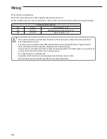
  For Indoor Power Cable, use the grade H07RN-F or H05RN-F materials.

Communication Cable

Home Server

0.75mm², 2wires

0.75mm², 2wires

Between Indoor unit and Outdoor unit Connection Cable Specifications(Common in use)

1-phase terminal block spec

3-phase terminal block spec

AC power : M5 screw

AC power : M4 screw

When installing the indoor unit in a computer room or network room,  

use the double shielded (Tape aluminum / polyester braid + copper )  

cable of FROHH2R type.

Communication : M3 screw

6.7

9.7

L

N

12

15

N

L3(T)

L2(S)

L1(R)

9.95

11.55

Communication : M3 screw

6.7

9.7

Summary of Contents for RC***MHXEA

Page 1: ...t Pump Mono Outdoor Unit installation manual imagine the possibilities Thank you for purchasing this Samsung product To receive more complete service please register your product at www samsung com register DB98 00000A 1 I F S E P G R D ...

Page 2: ...ementssetforthinthe Operating limits table includedinthemanual shallimmediatelyinvalidatethewarranty Donotusetheunitsifyouseesomedamagesontheunitsandrecognizesomethingbadsuchasloudnoisy smellofburning Inordertopreventelectricshocks firesorinjuries alwaysstoptheunit disabletheprotectionswitchandcontactSAMSUNG s technicalsupportiftheunitproducessmoke ifthepowercableishotordamagedoriftheunitisverynoi...

Page 3: ...anceoperationstobecarriedout Iftheunitsinstalledwithoutcomplyingwithproceduresdescribedinmanual additionalexpensescanbeaskedbecausespecial harnesses ladders scaffoldingoranyotherelevationsystemforrepairservicewillNOTbeconsideredpartofthewarrantyandwill bechargedtotheendcustomer Alwaysmakesurethatthepowersupplyiscompliantwithlocalsafetystandards Verifythatthevoltageandfrequencyofthepowersupplycompl...

Page 4: ...els NH200CHXEA NH300CHXEA Solar connected NH200CHXES NH300CHXES Option Product Line up Accessories Keep supplied accessories until the installation is finished Hand the installation manual over to the customer after finishing installation The quantities are indicated in parentheses Installation manual 1 Drain plug 1 Fastener nut 1 Rubber cover wire 2 Drain cap 1 Control Kit Domestic Hot Water tank...

Page 5: ...1 7 L950 Φ7 FP 1 7 L950 Φ7 FP 1 7 L950 Fan Motor Propeller Φ520 3 blade BLDC Inverter Propeller Φ520 3 blade BLDC Inverter Propeller Φ520 3 blade BLDC Inverter Flow Switch LPM 16 1 5 Magnetic decreasing 16 1 5 Magnetic decreasing 16 1 5 Magnetic decreasing Base Heater W 150 150 150 Refrigerant g 2 200 R410A 2 200 R410A 2 200 R410A Noise Heat Cool Pressure dB 64 62 64 62 64 62 Water Connection In O...

Page 6: ...e 48 plates Evaporator Φ7 FP 1 6 L850 Fan Motor Propeller Φ520 3 blade BLDC Inverter Flow Switch LPM 16 1 5 Magnetic decreasing Base Heater W 150 Refrigerant g 1 850 R410A Noise Heat Cool Pressure dB 63 60 Water Connection In Out Inch 1 0 1 0 Leaving Water Temperature C Cooling 5 25 Heating 25 55 Operating range Heat Cool C 20 35 10 46 Weight net Kg 83 Size WxHxD net mm 940 x 998 x 330 ...

Page 7: ...The application examples given below are for illustration purposes only When the SAMSUNG Air to Water Heat Pump system is used in series with another heat source e g gas boiler ensure that the return water temperature not exceed 55 C The unit is only to be used in a closed water system Application in an open water circuit can lead to excessive corrosion of the water piping SAMSUNG can not be put r...

Page 8: ...turn Header Under Floor Heating Coils T Supply Header T B Supply Header Radiators or Convectors Return Header Cylinder Unit Outdoor unit Room Thermostat Wireless Control Kit provided by SAMSUNG Wired Controller RF Receiver Hot water Supply From City Water Expansion Vessel P P F F T ...

Page 9: ...ENGLISH 9 Main Components Heat Pump for R410A 1 Fan Chassis RC090MHX 2 Fan Chassis RC120MHX RC140MHX RC160MHX 620 940 330 973 998 528 537 675 360 384 Dimensions Overall 620 330 360 384 940 1395 1420 ...

Page 10: ...10 Main Components Dimensions Water pipe 513 4 151 5 83 5 244 4 Unit mm Unit mm RC090MHX RC120MHX RC140MHX RC160MHX ...

Page 11: ...ENGLISH 11 NO Name Note 1 PHE 48P 2 Base Heater SUS316L 150W 3 Water fitting BSPP 1 Male Components RC090 ...

Page 12: ...12 Main Components NO Name Note 1 PHE 72P 2 Base Heater SUS316L 150W 3 Water Hose In Rubber Hose 4 Water Hose Out Rubber Hose 5 Water fitting BSPP 1 Male Components RC120 140 160 ...

Page 13: ...t temp sensor T S 2 For water inlet temp sensor T S 3 For PHE In temp T S 4 For PHE Out temp T S 5 For discharge temp T S 6 For Cond temp T S 7 For Ambient temp sensor S V Service valve inch Accum ACCUMULATOR PHE T S 3 T S 4 S V S V 4WAY v v T S 5 Comp Filter Filter Exp v v Accum T S 6 T S 7 T S 1 T S 2 ...

Page 14: ...et temp sensor T S 2 For water inlet temp sensor T S 3 For PHE In temp T S 4 For PHE Out temp T S 5 For discharge temp T S 6 For Cond temp T S 7 For Ambient temp sensor S V Service valve inch Accum ACCUMULATOR PHE T S 3 T S 4 S V S V 4WAY v v T S 5 Comp Filter HP s w Filter Exp v v Accum T S 6 T S 7 T S 1 T S 2 ...

Page 15: ... The outdoor unit must not be placed on its side or upside down as the compressor lubrication oil will run into the cooling circuit and seriously damage the unit Choose a location that is dry and sunny but not exposed to direct sunlight or strong winds Do not block any passageways or thoroughfares Choose a location where the noise of the Air toWater Heat Pump when running and the discharged air do...

Page 16: ...ce where corrosive gas such as sulfurous acid gas generates from the vent pipe or air outlet The copper pipe or connection pipe may corrode and refrigerant may leak The place where there is a danger of existing combustible gas carbon fiber or flammable dust The place where thinner or gasoline is handled This device must be installed according to the national electrical rules With an outdoor unit h...

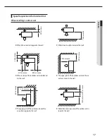
Page 17: ...l 300 or more 300 or more 600 or more When 3 sides of the outdoor unit are blocked by the wall 1500 or more 2000 or more The upper part of the outdoor unit and the air outlet is towards the wall 1500 or more 600 or more 300 or more The upper part of the outdoor unit and the air outlet is opposite the wall 300 or more When front and rear side of the outdoor unit is towards the wall ...

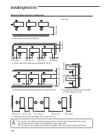
Page 18: ... unit is towards the wall When front and rear side of the outdoor unit is towards the wall When installing more than 1 outdoor unit The units must be installed according to distances declared in order to permit accessibility from each side either to guarantee correct operation of maintenance or repairing products The unit s parts must be reachable and removable completely under safety condition fo...

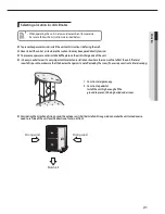
Page 19: ...installed on the roof you have to check the ceiling strength and waterproof the unit Outdoor unit installation Outdoor unit support When installing air guide duct Check and make sure that screws do not damage the copper pipe Secure air guide duct on guard fan 20mm Anchor bolt Outdoor Unit Base Surface Outdoor Unit Support Soft rubber designed to cut off vibration from rack to wall not supplied wit...

Page 20: ...eunitonaframe pleaseinstallawaterproofplatewithin150mmof theundersideoftheunitinordertopreventtheinvasionofwaterfromthelower direction 4 Wheninstallingtheunitinaplacefrequentlyexposedtosnow payspecialattention toelevatethefoundationashighaspossible 5 Ifyouinstalltheunitonabuildingframe pleaseinstallawaterproofplate fieldsupply within150mmoftheundersideoftheunit inordertoavoidthedrain waterdripping...

Page 21: ...owfallareasitisveryimportanttoselectaninstallationsitewherethesnowwillnotaffecttheunit Iflateral snowfallispossible makesurethattheheatexchangercoilisnotaffectedbythesnow Ifnecessaryconstructalateralcanopy Consideringthedirectionofstrongwind theoutdoorunitshallbeinstalled Strongwindcanmaketheunitturnedoverso needtosetsideoftheunitfacethedirectionofwind notfront 1 Constructalargecanopy 2 Constructa...

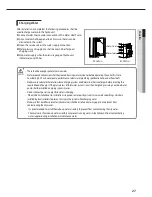
Page 22: ...alsfromeachothertopreventgalvaniccorrosion Becausebrassisasoftmaterial useappropriatetoolingfor connectingthewatercircuit Inappropriatetoolingwillcause damagetothepipes Be careful not to deform the unit piping by using excessive force when connecting the piping Deformation of the piping can cause the unit to malfunction Always use two wrenches spanners for tightening or loosening the water connect...

Page 23: ...emove contaminants during hours using a flushing unit or tap water pressure if it is adequate at 2 to 3 bar 4 Fill water into the hydro unit by opening service valves 5 Purge the air Fill with a flushing unit with sufficient capacity avoid aerating the water 6 Circulate for long enough to ensure that all air has been bled from the complete water piping system After installations commissioning shou...

Page 24: ...y The water pressure indicated on the manometer will vary depending on the water temperature The nominal water pressure in the system should remain about 1 0 bar at all times to avoid air entering the water system Air purging Make sure that air should be vented from the system at start up or after installing servicing The air vent valve must be opened during charging the water at least 2 turns in ...

Page 25: ...ed water volume 7m Actions required Pre pressure must be increased calculate the appropriate value following by Calculating the pre pressure of the expansion vessel Check if the water volume is lower than maximum allowed water volume Expansion vessel of the unit too small for the installation a Installation height difference height difference m between the highest point of the water circuit and th...

Page 26: ...PHE resistance by Glycol concentrate Changing Glycon concentration can cause the pressure drop of the system and it can leads to make flow rate rather slow Just in case performance degration installer shall be careful of flow rate changes 0 20 40 60 80 100 120 140 160 180 200 0 10 20 30 40 50 60 70 80 90 kPa LPM RC090 WATER EG 10 EG 20 WG 40 EG 45 0 20 40 60 80 100 120 140 160 180 200 0 10 20 30 4...

Page 27: ...erpumpperformance selectwaterplumbingspecificationandunderfloorloofs Makesuretocalculatethetotalresistanceofpipingsystemanddeterminethesizeofpipesbeforeselectingthe requiredheadofpumps Ifthepressurelossoftotalwatersystemisoverthandesignedpressure anexternalwater pumpshallbeinstalledonpipingsysteminseries Donotconnectpowersupplywhilewaterischarging Wheninitialinstallationorre installationisrequired...

Page 28: ...0 035W mK in order to prevent freezing on the outside water piping If the temperature is higher than 86 F 30 C and the humidity is higher than RH 80 then the thickness of the sealing materials should be at least 20 mm in order to avoid condensation on the surface of the sealing Installation of Filter Strainer is mandatory for water system The Filter or Strainer shall be located in front of inlet p...

Page 29: ...ions and then electrical connections If unit is uninstalled first disconnect electrical cables then refrigerant connections Connect the air conditioner to grounding system before performing the electrical connection When installing the unit you shouldn t use inter connection wire MCCB 3 ELCB 3 ELCB 1 Power cable 1 Control kit Outdoor Unit Communication cable Grounding Grounding Power cable Communi...

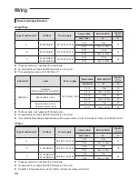
Page 30: ...er cable MAX LENGTH Type GL mm wires m A A RC090MHXEA 1Φ 220 240V 50Hz 4 0 3 10m 30 6 0 3 10m L 20m B RC120MHXEA 1Φ 220 240V 50Hz 4 0 3 10m 30 6 0 3 10m L 20m C RC140MHXEA RC160MHXEA 1Φ 220 240V 50Hz 4 0 3 10m 40 6 0 3 10m L 20m Power Cable Specifications Single Phase 3 Phase Type of outdoor unit Outdoor Power supply power cable MAX LENGTH Type GL mm wires m A A 3Φ 380 415V 50Hz 1 5 4 10m 20 2 5 4...

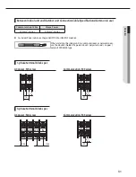
Page 31: ...tion Cable Specifications Common in use 1 phase terminal block spec 3 phase terminal block spec AC power M5 screw AC power M4 screw When installing the indoor unit in a computer room or network room use the double shielded Tape aluminum polyester braid copper cable of FROHH2R type Communication M3 screw 6 7 9 7 L N 12 15 N L3 T L2 S L1 R 9 95 11 55 Communication M3 screw 6 7 9 7 ...

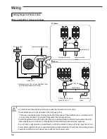
Page 32: ...nforyourapplication Ensurethatmainsupplyconnectionismadethroughaswitchthatdisconnectsallpoles withcontactgapofaleast3mm Devicesdisconnectedfromthepowersupplyshouldbecompletelydisconnectedintheconditionofovervoltagecategory Keepdistancesof50mmormorebetweenpowercableandcommunicationcable Wiring Wiring Diagram of Power Cable When using ELB for 1 phase and 3 phase N L ELB MCCB MCCB N L3 T L2 S L1 R Po...

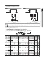
Page 33: ...mm inch Max mm inch Standard dimension mm inch Allowance mm inch Min mm inch 4 6 0 006 0 009 4 3 8 9 5 3 8 0 2 0 007 5 6 1 4 0 3 0 011 0 2 0 007 3 4 1 8 0 2 0 007 6 1 4 5 3 16 20 3 4 4 3 3 16 0 2 0 007 0 0 0 9 0 03 8 3 16 15 9 16 9 3 8 28 5 1 1 8 8 4 1 3 16 0 4 0 015 0 0 10 0 01 8 3 16 15 9 16 0 2 0 007 7 1 1 4 0 3 0 011 0 2 0 007 4 5 3 16 0 2 0 007 7 9 5 16 9 3 8 30 1 3 16 8 4 1 3 16 0 4 0 015 0 ...

Page 34: ...gether with refirgerant piping Remove all burrs at the edge of the knock out hole and secure the cable to the outdoor knock out using lining and bushing with an electrical insulation such as rubber and so on Must keep the cable in a protection tube Keep distances of 50mm or more between power cable and communication cable When the cables are connected through the hole remove the Plate bottom Conne...

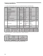
Page 35: ... mode 7 seg display Press K1 button twice Start Defrost test mode Press K1 button Stop Defrost test mode 7 seg display Condition 1 The outdoor temperature is under 10 C Condition 2 All the temperature conditions should meet the defrost conditions 4 After 12 minutes of stationary condition check each indoor unit air treatment Cooling mode indoor unit check Inlet air temp Outlet air temp From 10 C t...

Page 36: ...NoProtectivecontrol 1 Freezing 2 Non stopdefrosting 3 Over load 4 Discharge 5 Totalelectriccurrent Frequencystatus 0 Normal 1 Hold 2 Down 3 Up_limit 4 Down_limit 14 Thetemperatureofheatradiatingplate E Hundreds digit Tens digit Unitdigit 15 S Wcheck F Long push 1 Main micom version Year Hex Month Hex Date Tens digit Date Unit digit After short push 1 Inverter micom version Year Hex Month Hex Date ...

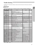
Page 37: ...40 Cooling operation is not available since the outdoor air temperature is lower than 5 C Cooling E441 12 MAIN INVERTER Outdoor unit BLDC Fan 1 or Fan 2 error FAN1 error E458 FAN2 error E475 13 MAIN INVERTER Comp Starting error E461 14 MAIN Primary Current Trip error E462 15 MAIN Over current trip PFC over current error Check OLP sensor E463 16 MAIN INVERTER IPM IGBT Module Over Current O C E464 1...

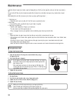
Page 38: ... When the Ph value is below 7 0 then oxidation of the glycol occurred the system should be drained and flushed thoroughly before severe damage occurs Make sure that the disposal of the glycol solution is done in accordance with relevant local and national regulation 1 Open the cap and turn the stop valve counterclockwise by using a hexagonal wrench 2 Turn it until the axis is stopped 3 Tighten the...

Page 39: ...gerant 3 If you cannot fully recharge the additional refrigerant while the outdoor unit is stopped use the key on PCB in the Heat Pump to run for recharging the remaining refrigerant Adding refrigerants in running condition 1 Press the function key for adding refrigerant 2 After 30 minutes of operation open the service valve on low pressure side in Heat Pump 3 Open the valve for low pressure side ...

Page 40: ...eofR 410A installer orrecognisedpersonwhichhasresponsabilityforfinalcheck hastoprovideamaintenancebook withalltheinformationrecordedaccordingtoREGULATION EC N 842 2006OFTHE EUROPEANPARLIAMENTANDOFTHECOUNCILof17May2006oncertainfluorinatedgreenhousegases a Factory refrigerant charge of the product see unit name plate b Additional refrigerant amount charged in the field Refer to the above information...

Page 41: ...41 Memo ...

Page 42: ...42 Memo ...

Page 43: ...43 AA Memo ...

Page 44: ... EEE Yönetmeliğine Uygundur This EEE is compliant with RoHS ...

Reviews: