background image

4. Troubleshooting

M382xND/M382xDW/M402xND

1

5

6

7

9

8

2

1

1

10

3

4

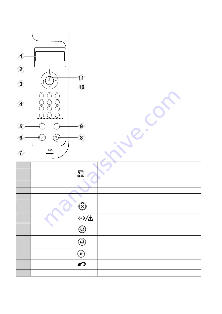
1

Display screen

Shows the current status and prompts during an operation.

2

Menu


Enters menu mode and scrolls through the available menus.

3

Arrow

Navigates available values by moving to the next or previous options.

4

Numeric keypad

Use the keypad to enter numbers and characters.

5

Eco

Enters eco mode to reduce toner consumption and paper usage.

6

Cancel

Stops current operation.

7

Status LED

Indicates the status of your machine.

8

Power

You can turn the power on and off with this button. Or wake up from
the power save mode.

Configuration sheet

Prints a demo page by pressing this button.

9

WPS

Configures the wireless network connection easily without a computer.

10

Back


Sends you back to the upper menu level.

11

OK

Confirms the selection on the screen.

4-2

Copyright© 1995-2016 SAMSUNG. All rights reserved.

Summary of Contents for ProXpress 402 Series

Page 1: ...er 1 33 SERVICEMANUAL Mono Laser Printer Contents 1 Precautions 2 Product Specifications 3 Disassembly and Reassembly 4 Troubleshooting 5 System Diagram 6 Reference Information Refer to the service manual in the GSPN see the rear cover for more information ...

Page 2: ...and Software 2 4 2 1 2 4 Paper Handling 2 5 2 1 2 5 Consumables 2 7 2 1 2 6 Maintenance Part 2 8 2 2 Product Description 2 9 2 2 1 Front View 2 9 2 2 2 Rear View 2 10 2 2 3 Paper Path 2 11 2 2 4 System layout 2 12 2 2 4 1 Feeding Part 2 13 2 2 4 2 Image Creation 2 15 2 2 4 3 Fuser unit 2 17 2 2 4 4 LSU Laser Scanning Unit 2 18 2 2 4 5 Drive Unit 2 19 2 2 5 Hardware configuration 2 20 2 2 5 1 Main ...

Page 3: ...3 3 3 3 Replacing the Main SVC parts 3 4 3 3 1 Left and Right Cover 3 4 3 3 2 Front Cover 3 5 3 3 3 Rear and Top Cover 3 6 3 3 4 Main Board 3 8 3 3 5 HVPS board 3 9 3 3 6 SMPS Board 3 10 3 3 7 Laser Scanning Unit LSU 3 10 3 3 8 Fuser Unit 3 11 3 3 9 Main Drive Unit 3 12 3 3 10 Feed Drive Unit 3 13 3 3 11 Pick Up_Regi_MP Clutch 3 13 3 3 12 Pick Up Roller 3 14 3 3 13 Transfer Roller 3 15 3 3 14 OPE ...

Page 4: ...ice SWS 4 23 4 1 7 Updating Firmware 4 25 4 1 7 1 Update the firmware by using the USB port 4 25 4 1 7 2 Update the firmware by using the network 4 26 4 1 8 Service Mode 4 28 4 2 Troubleshooting 4 32 4 2 1 Procedure of checking the symptoms 4 32 4 2 1 1 Basic Check List 4 33 4 2 2 Error Code and Troubleshooting 4 34 4 2 3 Image quality problem 4 62 4 2 4 Other errors 4 68 5 System Diagram 5 1 5 1 ...

Page 5: ...rements of DHHS 21 CFR chapter 1 Subchapter J for Class I 1 laser products and elsewhere is certified as a Class I laser product conforming to the requirements of IEC EN 60825 1 2014 Class I laser products are not considered to be hazardous The laser system and printer are designed so there is never any human access to laser radiation above a Class I level during normal operation user maintenance ...

Page 6: ...product this can cause electric shock Do not allow paper clips pins or other foreign objects to fall into the product these could cause a short circuit leading to an electric shock or fire hazard 5 Never touch the plugs on either end of the power cable with wet hands this can cause electric shock When servicing the product remove the power plug from the wall socket 6 Use caution when inserting or ...

Page 7: ...ition the machine near a humidifier or in front of an air conditioner Moisture and dust built up inside the machine can lead to overheating and cause a fire or cause parts to rust 11 Do not position the product in direct sunlight This will cause the temperature inside the product to rise possibly leading to the product failing to work properly and in extreme conditions could lead to a fire 12 Do n...

Page 8: ...ns 1 Replace parts carefully and always use Samsung parts Take care to note the exact location of parts and also cable routing before dismantling any part of the machine Ensure all parts and cables are replaced correctly Please carry out the following procedures before dismantling the product or replacing any parts 2 Ensure that power is disconnected before servicing or replacing any electrical pa...

Page 9: ...n get harm 3 When you move the printer use safe lifting and handling techniques This printer is heavy Use the lifting handles located on each side of the machine Back injury could be caused if you do not lift carefully 4 Ensure the printer is installed safely Ensure the printer is installed on a level surface capable of supporting its weight Failure to do so could cause the printer to tip or fall ...

Page 10: ...n the vicinity of the assembly 3 Use only a grounded tip soldering iron to solder or desolder ESDs 4 Use only an anti static solder removal device Some solder removal devices not classified as anti static can generate electrical charges sufficient to damage ESDs 5 Do not use Freon propelled chemicals When sprayed these can generate electrical charges sufficient to damage ESDs 6 Do not remove a rep...

Page 11: ...ipt3 PCL6 5e IBM ProPrinter EPSON SPL 4 Memory Std Max M332xND M382xD 128 MB 128 MB M382xND DW 128 MB 512 MB M402xND 256 MB 512 MB M402xNX 1GB 1GB 5 Interfaces High Speed USB 2 0 Wired Network M382xD Not Support M332xND M382xND M382xDW Ethernet 10 100 Base Tx M402xND M402xNX Ethernet 10 100 1G Base Tx Wireless Network M382xDW Only 802 11b g n 6 Consumables Integrated Toner System M3320ND M3820D M3...

Page 12: ...xNX Less than 15 Wh Average operating mode Less than 700 W Power Consumption Power save mode M332x M382x series M402xND Less than 1 1 Wh M382xDW Wi Fi Direct on Less than 2 8Wh off 1 6Wh M402xNX Less than 3 9 Wh Dimension W x D x H Set mm 366 5 x 368 x 256 5 mm 14 42 x 14 48 x 10 09 inches Weight Set Kg 10 Kg 22 04 lbs Recommended Monthly Printing Volume AMPV M332xND 1000 2500 pages M382x series 1...

Page 13: ... Up to 16 ipm in A4 17 ipm in Letter M382x series Up to 19 ipm in A4 20 ipm in Letter M402x series Up to 20 ipm in A4 21 ipm in Letter Ready Mode As fast as 6 5 sec FPOT Sleep Mode M332x series Less than 15 5 sec M382x 402x series Less than 18 sec Optical Standard 600 x 600 dpi Resolution Enhanced Up to 1 200 x 1 200 dpi effective output Emulation PostScript3 PCL6 5e IBM ProPrinter EPSON SPL Copyr...

Page 14: ...5 6 7 8 9 10 11 12 13 14 15 32 64 bit OpenSuSE 10 2 10 3 11 0 11 1 11 2 11 3 11 4 32 64 bit SuSE Linux Enterprise Desktop 10 11 32 64 bit Debian 4 0 5 0 6 0 32 64 bit Mandriva 2007 2008 2009 2009 1 2010 32 64 bit Ubuntu 6 06 6 10 7 04 7 10 8 04 8 10 9 04 9 10 10 04 10 10 11 04 32 64 bit Driver Supporting OS Unix HP UX 11 0 11i v1 11i v2 11i v3 PA RISC Itanium Sun Solaris 9 10 11 x86 SPARC Network ...

Page 15: ...t Cassette Tray 80g m 50 sheet Multi Purpose Tray 80g m Max Capacity M332xND 771 sheet 80g m with option cassette M382xD 251 sheet 80g m NOTE M382xD does not support the option cassette M382xND M382xDW M402xND M402xNX 820 sheet 80g m with option cassette Printing Max Size 216 x 356 mm 8 5 x 14 Min Size 76 x 127 mm 3 0 x 5 0 Capacity M382xND M382xDW M402xND M402xNX Plain Paper 50 sheets 80g m Envel...

Page 16: ...5 Media types Plain Paper Thin Thick Recycled Bond Cardstock Archive Media weight 16 43 lb 60 to 163 g m Optional Cassette Tray Sensing CST Open Paper Empty Capacity Face Down 150 sheets 80 g m Face Up 1 sheet Output Stacking Output Full sensing Yes Supporting Built in Media sizes A4 Letter Oficio Folio Legal Media types Plain Paper Thin Thick Recycled Bond Duplex Media weight 16 32 lb 60 to 120 g...

Page 17: ...X O O Laser Toner Cartridge MLT D203U Approx 15 000 pages X X O NOTE The yield of initial toner cartridge is approx 3 000 pages Declared cartridge yield in accordance with ISO IEC 19752 Separated Toner System Item Model Name Average yield M3325ND M3825D M3825ND M3825DW M4025ND M4025NX MLT D204S Approx 3 000 pages O O O MLT D204L Approx 5 000 pages O O O MLT D204E Approx 10 000 pages X O O Toner Ca...

Page 18: ...e replaced as instructed Item Part Code Life Tray1 Pick up roller JC73 00340A Approx 90 000 pages Tray1 Separation Reverse roller JC90 01063B Approx 60 000 pages Transfer roller JC66 02842A Approx 100 000 pages Fuser Unit JC91 01023A 110V JC91 01024A 220V Approx 90 000 pages Tray2 Pick up Forward roller Optional JC97 02259A Approx 200 000 pages Tray2 Separation Reverse roller Optional JC97 02259A ...

Page 19: ...ilable depending on model or country 0 011 12 13 0 10 09 8 1 2 3 7 6 5 4 1 Control Panel 2 Control board cover 3 Front cover 4 Paper level indicator 5 Tray 2 6 Tray 1 7 Multi purpose or manual feeder tray 8 Output tray 9 Paper width guides on a multi purpose or manual feeder tray 10 Toner cartridge NOTE M3320 M3820 M4020 series only 11 Toner cartridge NOTE M3325 M3825 M4025 series only 12 Imaging ...

Page 20: ...able depending on model or country 2 3 4 5 6 9 8 7 1 EDI OUTPUT 5V 1 EDI port 2 Network port 3 USB port 4 5V output port for IEEE 1284B parallel connector NOTE The optional IEEE 1284B parallel connector can be used by plugging in both the USB port and the 5V output port 5 Power switch 6 Power receptacle 7 Duplex unit 8 Rear cover 9 Tray back cover 2 10 Copyright 1995 2016 SAMSUNG All rights reserv...

Page 21: ... Product Specifications 2 2 3 Paper Path The following diagram displays the path the paper follows during the printing process 1 Simplex 2 Duplex 3 MP Copyright 1995 2016 SAMSUNG All rights reserved 2 11 ...

Page 22: ...ner cartridge Drive unit Transfer roller Fuser Cassette The Hardware part consists of the main control board power board operation panel PC Interface 1 2 3 4 7 6 8 5 11 10 9 1 LSU Laser Scanning Unit 2 Toner Cartridge 3 Regi Roller 4 MP 5 Feed Roller 6 Pick Up Roller 7 Cassette 8 Duplex Unit 9 Fuser 10 Exit Roller1 11 Exit Roller2 2 12 Copyright 1995 2016 SAMSUNG All rights reserved ...

Page 23: ...the paper size 3 2 1 2 Pick up Reverse Retard roller When pickup takes place the pickup roller rotates to separate and transport the paper The pickup roller rotates when the pickup clutch is activated The retard roller serve to make sure that a single sheet of paper is moved to the paper path and the paper is moved as far as the registration roller by the work of the feed roller The following is a...

Page 24: ...hment and the duplex feeding takes a side feeding method Usable papers are A4 letter and legal size paper For removing a jam occurred in a front part it is designed to open a cassette and a guide It is designed to open a rear cover to remove a jam in a rear part If a face up tray is open the duplex option cannot be used 4 A 0 0 6 SCF Second Cassette Feeder It is the same method with the main casse...

Page 25: ...latent image by discharging on the surface of the OPC drum The negatively charged toners are attracted to the latent image due to and electric field The toners real image on the OPC drum are moved to the transfer media by the positive bias applied to the transfer roller 1 Charging the OPC drum The scorotron gives the drum negative charges 2 Laser exposure Light produced by a laser diode irradiates...

Page 26: ...p 10 30 Humidity 20 85 RH Developing Method Non magnetic 1 element contacting method Toner Non magnetic 1 element shatter type toner Toner Residual Sensor Dot count with zCRUM OPC Cleaning Collect the toner by using cleaning blade Handling of wasted toner Collect the wasted toner in the cleaning frame by using cleaning blade OPC Drum Protecting Shutter None Classifying device for toner cartridge I...

Page 27: ...ture 190 5 2 Thermistor It is a temperature detecting sensor Temperature Resistance 7 KΩ 180 3 Heat roller The heat roller transfers the heat from the lamp to apply a heat on the paper The surface of a heat roller is coated with Teflon so toner does not stick to the surface 4 Pressure roller A pressure roller mounted under a heat roller is made of a silicon resin and the surface also is coated wit...

Page 28: ...l is created when the laser beam from LSU reaches the end of the polygon mirror and the signal is sent to the controller The controller detects the HSYNC signal to adjust the vertical line of the image on paper In other words after the HSYNC signal is detected the image data is sent to the LSU to adjust the left margin on paper The one side of the polygon mirror is one line for scanning OPC Drum P...

Page 29: ...e units that is assembled to the right side of the machine The main drive unit consists of a BLDC motor a clutch various gears for OPC fuser exit feed etc The feed drive unit consists of 2 gears for MP feed Main Drive Unit Feed Drive Unit Copyright 1995 2016 SAMSUNG All rights reserved 2 19 ...

Page 30: ... D N G V 3 3 n e p O _ r e v o C _ V 3 3 N A L W H S A L F D N A N B M 8 2 1 P M h c t u l C P M r o s n e S AMBIENT GND 1 2 m m 2 8 2 N C R I A P M E T B U H B S U r e v o C n e p O t n e i b m A p m e T r o s n e S z H K 7 2 3 K L C C T R z H M 5 2 LED4 Re s e rve d nKEY_4 Re s e rve d LED_ECO LED_3_1_BLUE Re s e rve d nKEY_ECO LED_P OWER nKEY_P OWER GND 5V nKEY_CANCEL LED_READY LED_ERROR LED_TO...

Page 31: ..._P _RE GI 3 3 VS GND nS E NS _P _F E ED 1 2 3 4 5 6 7 8 9 CN6 2mm SENSOR 24 VS MP _ CLUTC H 3 3 VS GND SE NS_ M P 1 2 3 4 5 CN19 2mm MP FEED Sensor 24VS GND THV_RE AD nTHV_E N P WM_THV P WM_DE V_DC P WM_MHV P WM_FUS E R_BIAS GND GND 3 3V 3 3V_Cove r_Ope n CN35 1 5mm SCF_IF CLK_ LSU_ M OT n R E ADY_ LSU n LSU_ MO T_ EN GND 2 4 VS LSU Dual Beam 24V1 24V1 5V_S US P nRS T_S CF S CF_TXD S CF_RXD nS CF_...

Page 32: ...2 Product Specifications Main Circuit Board Locations The following diagrams show the locations of the printer circuit boards 2 22 Copyright 1995 2016 SAMSUNG All rights reserved ...

Page 33: ... External DDR3 SODIMM 512MB Not supply for M3820D 3825D Ethernet PHY Network printing NAND Flash Program memory 128MB The Main Controller manages an Electro photography system controls the Video Data of printing images from Main Board to LSU provides high voltages and PWMs adjusts temperature in the fusing system reads sensor signals and controls SCF option The Main controller also controls OPE an...

Page 34: ...NER CRUM Only for M3325ND 3825ND 3825DW 4025ND 7 WLAN Only for M3820DW 3825DW 8 OUTBIN FULL REAR COVER OPEN 9 NETWORK Not apply for M3820D 3825D 10 USB DEVICE No Description 11 PARALLEL PWR 12 EXIT SENSOR 13 AIR TEMP 14 FAN SMPS 15 MAIN MOTOR 16 SCF option 17 DEBUG 18 SMPS SIGNAL 19 SMPS POWER 20 MP Not apply for M3320ND 3325ND 3820D 3825ND 21 LSU 22 FAN MAIN 23 HVPS 24 SENSOR I F 25 DDR3 SO DIMM ...

Page 35: ...D XIP SL M3820ND XSA SL M3820ND XSG SL M3820ND XSS JC92 02832E 220V Model SL M3825DW SEE SL M3825DW STS JC92 02832F 220V Model SL M3825ND SEE SL M3825ND STS SL M3825ND XIL JC92 02832D 220V Model SL M4020ND SL M4020ND ETS SL M4020ND GOV SL M4020ND KOY SL M4020ND SAU SL M4020ND SEE SL M4020ND STS SL M4020ND XBG SL M4020ND XBH SL M4020ND XEV SL M4020ND XFA SL M4020ND XIP SL M4020ND XSA SL M4020ND XSG...

Page 36: ...del SL M3820ND TED SL M3820ND XAA SL M3820ND XAX SL M3820ND XAZ JC92 02896A 110V Model SL M3825DW XAA JC92 02895A 110V Model SL M3820DW XAA SL M3820DW XAX SL M3820DW XAZ JC92 02894A 110V Model SL M4025ND XAZ SL M4025ND XBG JC92 02893A 110V Model SL M4020ND XAA SL M4020ND XAX SL M4020ND XAZ JC92 02892A 110V Model 2 26 Copyright 1995 2016 SAMSUNG All rights reserved ...

Page 37: ...hernet PHY Network printing NAND Flash Program memory 512MB MicroSD Memory 4GB The main controller manages an Electro photography system controls the Video Data of printing images from Main Board to LSU provides high voltages and PWMs adjusts temperature in the fusing system reads sensor signals and controls SCF option The main controller also controls OPE and N W PHY USB Device Main Controller Di...

Page 38: ...COVER OPEN 7 EDI 8 ETHERNET 9 USB DEVICE 10 PARALLEL PWR 11 DEBUG MAIN 12 DEBUG OPE 13 EXIT SENSOR No Description 14 MAIN MOTOR 15 AIR TEMP 16 FAN SMPS 17 SCF 18 SMPS SIGNAL 19 SMPS POWER 20 MP 21 LSU 22 FAN MAIN 23 HVPS 24 COVER OPEN SENSOR 25 DIRECT USB 26 DDR3 SO DIMM Part Code Information M4020NX JC92 02679A M4025NX JC92 02678A 2 28 Copyright 1995 2016 SAMSUNG All rights reserved ...

Page 39: ...icates with main controller via UART USB M3320ND 3325ND 3820D 3825D model OPE is composed of LEDs and KEYs without LCD OPE Controller Diagram OPE Controller Image M332xND M382xD M382xND DW M402xND M402xNX Part Code JC92 02609A PBA Name OPE LED Part Code JC92 02608A PBA Name OPE LCD 1 Part Code JC92 02610A PBA Name PBA OPE MAIN 2 Part Code JC07 0017A PBA Name LCD 3 Part Code JC92 02609A PBA Name OP...

Page 40: ... data from the USB and Network port There are four kinds of SO DIMM PBA 128MB M3320ND 3325ND 3820D 3825D 3820ND 3825ND 3820DW 3825DW 256MB M4020ND 4025ND 512MB Option only for M332xND M382xND M382xDW M402xND 1GB Option only for M402xNX Information Part Code 128MB JC92 02473A 256MB JC92 02472A 512MB JC92 02472B 1GB JC92 02512A Part Name PBA RAM DIMM 2 30 Copyright 1995 2016 SAMSUNG All rights reser...

Page 41: ...is installed at the USB Host Channel of main controller PBA Information Part Code JC92 02510A Part Name PBA WNPC 2 2 5 6 SCF PBA Optional The SCF PBA is the SCF control board It use UART communication with main controller UPD70F3824 is used as a microcontroller Information Part Code JC92 02539B Part Name PBA SCF Copyright 1995 2016 SAMSUNG All rights reserved 2 31 ...

Page 42: ...20 M4020 series use zCRUM PBA ProXpress M3325 M3825 M4025 series use zCRUM PBA OPC CRUM and CRUM JOINT PBA CRUM PBA uses I2C communication with main controller M3320 M3820 M4020 series M3325 M3825 M4025 series 2 32 Copyright 1995 2016 SAMSUNG All rights reserved ...

Page 43: ... power input Specification 1 AC 110V 93 5V 137V or AC 220V 187V 275V 2 Output Current 5V 1 6A 24V 1 8A 3 Output Power 5V 8 16W 24V 43 2W 4 Heat Lamp Capacity 850W Information 110V 220V SEC CODE JC44 00095D JC44 00096D PBA NAME SMPS V1 SMPS V2 Connection 1 INPUT_AC 2 Fuser_AC Output 3 SMPS Control Signal from Engine PBA 4 OUTPUT_5V 24V to DC POWER PBA Copyright 1995 2016 SAMSUNG All rights reserved...

Page 44: ...ltage channels which includes MHV DEV BLADE SUPPLY OPC THV and FUSER BIAS Connection 1 Main Interface 2 MHV 1240V 3 DEV 338V 4 BLADE 389V 5 SUPPLY 489V 6 OPC 51V 7 THV 1315V 1000V 8 FUSER BIAS 240V Information Part Code JC44 00197A Part Name HVPS 2 34 Copyright 1995 2016 SAMSUNG All rights reserved ...

Page 45: ...aper does not clear the sensor after predetermined period of time After the leading edge of the paper passes the feed sensor the paper cannot reach the exit sensor after predetermined period of time The paper exists between the feed sensor and the exit sensor JAM 2 The trailing edge of the paper does not clear the exit sensor within a predetermined 2 2 6 2 Transfer The charging voltage developing ...

Page 46: ...it is higher than the specified temperature and the temperature state is detected for a specific duration then the engine defines Over Heat Error When this error is detected the engine stops all functions and keeps it at the error state Also the engine informs the error status of the main system so it can take appropriate action and then the error message is displayed at LCD window or LED informin...

Page 47: ...nslates the received document to a Printing Command language which printer can understand and transfers data to spooler 3 Stand alone Application offers the various printing application such as Easy Printer Manager Printer Status in Window system 4 Web based Application offers the same functions as Stand alone Application in Web environment Firmware is made up of 1 Application Emulation that is a ...

Page 48: ...f printing job printer administration Status monitor to monitoring the printer status by real time in Web independent environment on OS 3 Stand alone Application that is a similar Window software as same as above 2 4 Port Monitor that manages the network communication between spooler and Network Interface Card or various additional application and Network Interface Card this is at first make commu...

Page 49: ...nd start selected one After emulation job end Kernel sends the output bit map data to Engine using Printer Video Controller by clock type for LSU Engine print the received data to required paper with the sequential developing process 2 Case of using Network Interface Card After user start to print the wanted document to PCL string or compressed GDI bit map data Driver translate the all graphic dat...

Page 50: ...r unit malfunction 3 1 2 Precautions when handling PBA Static electricity can damage a PBA always used approved anti static precautions when handling or storing a PBA Precautions when moving and storing PBA 1 Please keep PBA in a conductive case anti static bag or wrapped in aluminum foil 2 Do not store a PBA where it is exposed to direct sunlight Precautions when replacing PBA 1 Disconnect power ...

Page 51: ...tches Many of the parts are held in place with plastic latches The latches break easily release them carefully To remove such parts press the hook end of the latch away from the part to which it is latched Copyright 1995 2016 SAMSUNG All rights reserved 3 2 ...

Page 52: ...REW TAPTYPE BH S M3 L6 ZPC WHT SWRCH18A 3 6003 000282 FUSER SCREW TAPTYPE BH B M3 L8 ZPC BLK SWRCH18A 4 6003 000269 DRIVE SCREW TAPTYPE BH S M3 L6 ZPC WHT SWRCH18A 6 6003 000196 SCREW TAPTYPE PWH B M3 L10 NI PLT SWRCH18A 38 6003 000261 SCREW TAPTYPE BH B M3 L6 ZPC WHT SWRCH18A 3 6003 000301 FRAME ETC SCREW TAPTYPE BH S M4 L6 ZPC WHT SWRCH18A 1 6006 001078 FRAME ETC SCREW TAPTYPE PH WSP B M3 L10 ZP...

Page 53: ...in SVC parts 3 3 1 Left and Right Cover 1 Remove the cassette 2 Open the front cover Remove the toner cartridge 3 Remove the left cover by releasing hooks 4 Remove the right cover by releasing hooks Copyright 1995 2016 SAMSUNG All rights reserved 3 4 ...

Page 54: ...Cover 1 Remove the cassette and toner cartridge 2 Remove the right cover by releasing hooks 3 Unplug the connector connecting the front cover 4 Remove the front cover by releasing both hooks 3 5 Copyright 1995 2016 SAMSUNG All rights reserved ...

Page 55: ...cover Refer to 3 3 1 2 Unplug the OPE connector from main board 3 Remove 2 screws from the front 4 Remove the duplex unit 5 Remove the rear cover by releasing the right hook 6 Remove 2 screws 7 Lift up and release the top cover Copyright 1995 2016 SAMSUNG All rights reserved 3 6 ...

Page 56: ...3 Disassembly and Reassembly 8 Remove the top inner cover after removing 4 screws 3 7 Copyright 1995 2016 SAMSUNG All rights reserved ...

Page 57: ...bly and Reassembly 3 3 4 Main Board 1 Remove the right cover Refer to 3 3 1 2 Unplug all connectors on the main board 3 Remove 4 screws 4 Release the main board Copyright 1995 2016 SAMSUNG All rights reserved 3 8 ...

Page 58: ...bly and Reassembly 3 3 5 HVPS board 1 Remove the right cover Refer to 3 3 1 2 Remove 5 screws 3 Unplug the connector on the HVPS board 4 Release the HVPS board 3 9 Copyright 1995 2016 SAMSUNG All rights reserved ...

Page 59: ... 3 1 2 Unplug all connectors on the SMPS board 3 Remove 4 screws 4 Release the SMPS board 3 3 7 Laser Scanning Unit LSU 1 Remove the top cover Refer to 3 3 3 2 Unplug 2 flat cables from the LSU 3 Remove 3 screws 4 Release the LSU Copyright 1995 2016 SAMSUNG All rights reserved 3 10 ...

Page 60: ...user unit has cooled 1 Remove the rear cover Refer to 3 3 3 2 Open the Frame Rear by pushing both green points 3 Remove the Frame Rear by releasing both hooks 4 Remove the exit sensor holder after removing 2 screws 5 Remove 4 screws 6 Release the fuser unit CAUTION When reassembling the fuser unit do not forget to tighten these screws 3 11 Copyright 1995 2016 SAMSUNG All rights reserved ...

Page 61: ...1 2 Remove the Bar coupler 3 Remove the main drive unit after removing 6 screws NOTE When reassembling the main drive unit tighten 6 screws in order as shown above 4 Unplug the connector form the main motor 5 Release the main drive unit Copyright 1995 2016 SAMSUNG All rights reserved 3 12 ...

Page 62: ...fer to 3 3 9 2 Release the feed drive unit after removing 2 screws and 1 E ring 3 3 11 Pick Up_Regi_MP Clutch 1 Remove the feed drive unit Refer to 3 3 10 2 For the clutch to require replacement unplug the connector then replace it 3 13 Copyright 1995 2016 SAMSUNG All rights reserved ...

Page 63: ...isassembly and Reassembly 3 3 12 Pick Up Roller 1 Remove the cassette 2 Remove the duplex unit 3 Pull the small tap down then release the pick up roller Copyright 1995 2016 SAMSUNG All rights reserved 3 14 ...

Page 64: ...ving 4 screws 3 Release the LSU bracket after removing 4 screws 4 Push the transfer roller holder to the center and release it 5 Remove the transfer roller 3 3 14 OPE Board First remove the top cover Refer to 3 3 3 Except NX model 1 Release the OPE board after removing 5 screws 3 15 Copyright 1995 2016 SAMSUNG All rights reserved ...

Page 65: ...OVER PATH 2 Release the FFC cable from the COVER TOP Separate the OPE ASSY from the COVER TOP 3 Release the OPE cover after removing 4 screws 4 Disconnect the FFC cable and harness 5 Disconnect the LCD FFC cable 6 Remove the GROUND OPE Copyright 1995 2016 SAMSUNG All rights reserved 3 16 ...

Page 66: ... top inner cover Refer to 3 3 3 3 Remove 3 screws 4 Unplug the connector then release the MP unit 5 Separate the MP lower from the MP upper 3 3 16 Bin full sensor 1 Remove the top cover Refer to 3 3 3 2 Release the bin full sensor after unplugging the connector 3 17 Copyright 1995 2016 SAMSUNG All rights reserved ...

Page 67: ...RAME BOTTOM after removing 4 screws 3 Remove the sensor cover after removing 2 screws 4 For the sensor to require replacement unplug the connector then replace it 5 Remove the sensor cover after removing 2 screws 6 Unplug the connector then release the empty sensor Copyright 1995 2016 SAMSUNG All rights reserved 3 18 ...

Page 68: ...and Reassembly 3 3 18 Reverse Roller 1 Remove the cassette 2 Open the COVER CASSETTE 3 Release the reverse roller Assy 4 Release the reverse roller from its holder 3 19 Copyright 1995 2016 SAMSUNG All rights reserved ...

Page 69: ... SCF Right Cover 1 Remove 2 screws 2 Release the SCF right cover 3 3 19 2 SCF Main Board 1 Remove the SCF right cover Refer to 3 3 19 1 2 Unplug all connectors on SCF main board 3 Remove 4 screws 4 Release the SCF main board Copyright 1995 2016 SAMSUNG All rights reserved 3 20 ...

Page 70: ...motor connector 3 Remove 4 screws 4 Release the SCF main motor 3 3 19 4 SCF Clutch 1 Remove the SCF right cover Refer to 3 3 19 1 2 Unplug the clutch connector 3 Remove 2 E Rings and 2 Bushes 4 Remove 2 screws 5 Release the clutch bracket 6 Remove the SCF clutch 3 21 Copyright 1995 2016 SAMSUNG All rights reserved ...

Page 71: ...te 2 See the bottom of the SCF Unit 3 Release the pick up forward roller while pulling the small tap 3 3 19 6 SCF Reverse Roller 1 Remove the SCF cassette 2 Open the cassette cover 3 Release the reverse roller while pulling the small tap Copyright 1995 2016 SAMSUNG All rights reserved 3 22 ...

Page 72: ...fer to 3 3 19 4 3 Unplug the main motor connector 4 Remove 4 screws 5 Remove the SCF main drive unit 3 3 19 8 SCF Lift Assy 1 Remove the SCF right cover Refer to 3 3 19 1 2 Remove the SCF main board Refer to 3 3 20 2 3 Open the harness clamp 4 Remove 4 screws 5 Release the SCF Lift Assy 3 23 Copyright 1995 2016 SAMSUNG All rights reserved ...

Page 73: ...ve the SCF right cover Refer to 3 3 19 1 2 Remove the SCF main drive unit Refer to 3 3 19 7 3 Unplug the connectors from the right side 4 Remove the front cover 5 Remove 4 screws 6 Release the SCF Pick Up Unit Copyright 1995 2016 SAMSUNG All rights reserved 3 24 ...

Page 74: ...mbly and Reassembly 3 3 19 10 SCF Pick Up_Empty_Feed Sensor 1 Remove the SCF Pick Up Unit Refer to 3 3 19 9 2 Remove the sensor after unplugging the connector 3 25 Copyright 1995 2016 SAMSUNG All rights reserved ...

Page 75: ... various types of control panels Some features and optional goods may not be available depending on model or country M332xND M382xD 1 2 3 4 5 6 1 Toner LED Shows the status of the toner 2 Eco Enters eco mode to reduce toner consumption and paper usage 3 Configuration sheet Prints a demo page by pressing this button 4 Cancel Stops current operation 5 Power You can turn the power on and off with thi...

Page 76: ... characters 5 Eco Enters eco mode to reduce toner consumption and paper usage 6 Cancel Stops current operation 7 Status LED Indicates the status of your machine 8 Power You can turn the power on and off with this button Or wake up from the power save mode Configuration sheet Prints a demo page by pressing this button 9 WPS Configures the wireless network connection easily without a computer 10 Bac...

Page 77: ... v w w x x y y 1 Display screen Displays the current status and allows you to access available menus 2 Cancel Stops current operation 3 Power Turns the power on or off or wakes up the machine from the power save mode 4 Status LED Indicates the status of your machine Copyright 1995 2016 SAMSUNG All rights reserved 4 3 ...

Page 78: ...hed its estimated cartridge life It is recommended to replace the toner cartridge The cover is opened Close the cover There is no paper in the tray when receiving or printing data Load paper in the tray The machine has stopped due to a major error Check the display message and refer to troubleshooting chapter A paper jam has occurred Blinking The machine is connecting to a wireless network On The ...

Page 79: ...ring the paper pull the jammed paper out slowly and gently In tray 1 1 Pull out tray 1 2 Remove the jammed paper by gently pulling it straight out 3 Insert tray 1 back into the machine until it snaps into place Copyright 1995 2016 SAMSUNG All rights reserved 4 5 ...

Page 80: ...l out tray 2 2 Remove the jammed paper from the machine If the paper does not move when you pull or if you do not see the paper in this area stop and go to the next step 3 Pull tray 1 half way out 4 6 Copyright 1995 2016 SAMSUNG All rights reserved ...

Page 81: ...ight up and out 5 Insert the trays back into the machine In the multi purpose tray 1 If the paper is not feeding properly pull the paper out of the machine 2 Open and close the front cover Copyright 1995 2016 SAMSUNG All rights reserved 4 7 ...

Page 82: ...Inside the machine M3320 M3820 M4020 series NOTE 1 Open the front cover 2 Pull the laser toner cartridge out 3 Remove the jammed paper by gently pulling it straight out 4 8 Copyright 1995 2016 SAMSUNG All rights reserved ...

Page 83: ...ert the laser toner cartridge 5 Close the front cover Inside the machine M3325 M3825 M4025 series NOTE 1 Open the front cover 2 Pull out the toner cartridge and imaging unit Copyright 1995 2016 SAMSUNG All rights reserved 4 9 ...

Page 84: ...4 Troubleshooting 3 Remove the jammed paper by gently pulling it straight out 4 Insert the imaging unit and toner cartridge 5 Close the front cover 4 10 Copyright 1995 2016 SAMSUNG All rights reserved ...

Page 85: ... machine 1 Open the MP Tray 2 Close the MP Tray to eject the jammed paper from the machine 3 Gently pull the paper out of the output tray If you do not see the jammed paper or if there is any resistance when you pull stop and go to the next step Copyright 1995 2016 SAMSUNG All rights reserved 4 11 ...

Page 86: ...bleshooting 4 Open the rear cover 5 Pull down the both fuser levers 6 Open the fuser jam cover 7 Remove the jammed paper by gently pulling it straight out 4 12 Copyright 1995 2016 SAMSUNG All rights reserved ...

Page 87: ...4 Troubleshooting 8 Close the fuser jam cover 9 Pull up the both fuser levers 10 Close the rear cover Copyright 1995 2016 SAMSUNG All rights reserved 4 13 ...

Page 88: ...ove the jammed paper from the duplex unit If the paper does not come out with the duplex unit remove the paper from the bottom of the machine 3 Insert the duplex unit into the machine If you still do not see the paper go to the next step 4 14 Copyright 1995 2016 SAMSUNG All rights reserved ...

Page 89: ...bleshooting 4 Open the rear cover 5 Pull down the both fuser levers 6 Open the fuser jam cover 7 Remove the jammed paper by gently pulling it straight out Copyright 1995 2016 SAMSUNG All rights reserved 4 15 ...

Page 90: ...4 Troubleshooting 8 Close the fuser jam cover 9 Pull up the both fuser levers 10 Close the rear cover 4 16 Copyright 1995 2016 SAMSUNG All rights reserved ...

Page 91: ...mation Configuration on the control panel Supplies Information report You can print supplies information page It shows consumable unit life status and toner using status M332xND M382xD Press and hold Cancel button for about 6 seconds until the green LED stops blinking and release M382xND M382xDW M402xND Select Menu Information Supplies Info on the control panel Usage Counter You can print a usage ...

Page 92: ...our machine for the best print quality Before you set the altitude value determine the altitude where you are 1 High 3 2 High 2 3 High 1 4 Normal 0 5 000 m 16 404ft 3 000 m 9 842ft 2 000 m 6 561ft 1 000 m 3 280ft 4 3 2 1 You can set the altitude value from Device Settings in Samsung Easy Printer Manager program For Windows and Mac users you set from Samsung Easy Printer Manager Switch to advanced ...

Page 93: ...od mm Phenomenon Defective part 1 1st Pressure roller 62 8 mm Background 2 2nd Pressure roller 37 7 mm Background 3 Heat roller 77 8 mm Black spot and fuser ghost Fuser unit 4 Charge roller 34 5 mm Black spot 5 Developer roller 37 mm Horizontal band 6 OPC drum 76 mm White and Black spots 7 Supply roller 69 57 mm Horizontal band Laser Toner cartridge or Imaging Unit 8 Transfer roller 47 1 mm Ghost ...

Page 94: ... to conveniently use your Samsung machine Samsung Easy Printer Manager provides two different user interfaces for the user to choose from the basic user interface and the advanced user interface Switching between the two interfaces is easy just click a button Understanding Samsung Easy Printer Manager To open the program For Windows Select Start Programs or All Programs Samsung Printers Samsung Ea...

Page 95: ...e remaining toner level and paper The information will vary based on the machine selected Some machines do not have this feature 6 Order Supplies Click on the Order button from the supply ordering window You can order replacement toner cartridge s from online Advanced settings user interface overview The advanced user interface is intended to be used by the person responsible for managing the netw...

Page 96: ...task bar Icon Mean Description Normal The machine is in ready mode and experiencing no errors or warnings Warning The machine is in a state where a soft error has occurred For example a toner low status which may lead to toner empty status Error The machine has at least one hard error such as out of paper fuser error etc Machine does not have ability to come to ready without customer intervention ...

Page 97: ...ork connected SWS overview SyncThru Web Service SWS accepts HTTP request via port 80 as normal web servers provides interface to users information of networked printers and allow to configure the setting of printers is able to provide more complicated options than Local UI for printer configuration Connection Procedure 1 Open the Web browser and input IP address of machine Click Login 2 Log in Adm...

Page 98: ...security Firstly you have to login to SWS 1 Click Direct Print Configuration in the pop up windows when clicking Direct Print 2 In the Services Menu check Direct Print Or 1 Click System Security in the Security menu 2 Select Feature Management in the left frame 3 In the Services Menu check Direct Print 4 24 Copyright 1995 2016 SAMSUNG All rights reserved ...

Page 99: ...re by using the USB port Upgrading preparations usblist2 exe Tool which sends firmware data to printer Firmware file to update Upgrade Procedure 1 Turn the machine off 2 Connect USB cable to printer 3 Turn the machine on Check if the printer is the ready status 4 Drag the firmware file and Drop down on the usblist2 exe And then firmware update will be started automatically 5 When upgrading is comp...

Page 100: ...r Wireless Network connection is established Firmware file to update Upgrade Procedure 1 Open the Web browser and input IP address of machine Click Login 2 Log in Admin Mode ID admin PW sec00000 3 Select Maintenance menu and click upgrade wizard 4 26 Copyright 1995 2016 SAMSUNG All rights reserved ...

Page 101: ...r button and press next button 5 SyncThru will check verify firmware file and compare version and press next button 6 Machine starts upgrading SyncThru will return home page after upgrading is completed Copyright 1995 2016 SAMSUNG All rights reserved 4 27 ...

Page 102: ...nu 3 Select Tech Mode M402xNX 1 Push the on the touch screen while pushing the stop button 2 Select the Diagnostics 3 Input the password 1934 b Tech mode menu Depth1 Depth2 Depth3 Depth4 Menu Map Configuration Supplies Info Usage Counter Error Info Job Duty Memory Usage Information Report Assert History 106 Dev Bias NVM Read Write 107 ATTR Bias 100 Motor 101 Clutch 102 Sensor 105 MHV Bias 106 Dev ...

Page 103: ...tus and toner using status Usage Counter It contains the total number of pages printed Error Info It shows various kinds of errors which can be occurred in machine It also store history error count how many errors are issued Job Duty It shows printing usage by print job duty Memory Usage It shows memory usage d Diagnostics NVRAM Read Write This menu can change a configuration value for engine firm...

Page 104: ...V Bias Black MHV bias voltage on at normal drive level On Off 106 0030 0030 K Dev Bias Black Dev bias voltage on at normal drive level On Off 107 0030 0030 K THV Bias Black THV bias voltage on at normal drive level On Off 107 0031 0031 K THV Bias Black THV bias voltage on at normal drive level On Off 107 0070 0070 K THV Bias R Detect what the THV value is on the THV Roller Numeric 3 digits 109 000...

Page 105: ...er convenience for replacing the imaging unit Clear Counts This function resets the count information for selected item Engine Footer This function is for monitoring of the engine status If you perform this function at printing the setting value for engine is shown on the bottom of the printed page F W Upgrade The function is to upgrade the firmware by using usblist exe file When updating firmware...

Page 106: ...etailed description of the problem from the customer Power On Red LED on Error message is displayed OPE LED Green OK Print test page Printing quality is nomal Refer to Solution of Image Problem See the troubleshooting for error code END No Power Power Module error Main PBA OPE LED ON 4 32 Copyright 1995 2016 SAMSUNG All rights reserved ...

Page 107: ...peatedly at a specific point in the Paper Path Open the fuser cover Jam clear Dismantle the machine and carefully inspect the region where the jam occurs Especially check if paper fragments are caught in the Fuser 4 Print the Information Page Configuration Try printing a test page from a computer If there is an error check cables and driver installation 5 Check the Print Quality Is there are a Pri...

Page 108: ...1 1711 Error C1 1711 Call for Service P 4 38 C1 1712 Error C1 1712 Call for Service P 4 38 C2 1110 Prepare new cartridge P 4 39 C2 1120 Replace new cartridge P 4 39 C2 1150 Replace new cartridge P 4 39 C2 1160 Replace new cartridge P 4 39 C2 1170 Replace new cartridge P 4 39 C2 1411 Install toner P 4 39 C2 1512 Not Compatible Toner cartridge P 4 40 C2 1710 Error C2 1710 Call for Service P 4 40 C2 ...

Page 109: ... bin full Remove paper P 4 56 S2 3310 Error S2 3310 Turn off then on P 4 57 S2 3311 Error S2 3311 Turn off then on P 4 57 S2 3312 Error S2 3312 Turn off then on P 4 57 S2 3313 Error S2 3313 Turn off then on P 4 57 S2 3314 Error S2 3314 Turn off then on P 4 57 S2 3315 Error S2 3315 Turn off then on P 4 57 S2 3316 Error S2 3316 Turn off then on P 4 57 S2 3317 Error S2 3317 Turn off then on P 4 57 S2...

Page 110: ...ector on main board is connected properly Reconnect it 4 OPC coupler has overloaded After removing the toner cartridge imaging unit rotate the OPC coupler If there is any damage the OPC coupler can t rotate well Replace the toner cartridge imaging unit 5 Remove the left cover 6 Remove the main drive unit Refer to 3 3 9 7 The main BLDC motor is defective a Unplug the connector from the motor carefu...

Page 111: ...rtridge If its life is at the end turn the machine off and replace the toner cartridge with new one Error Code C1 1310 C1 1411 Error message Error C1 1310 Install toner Install toner Symptom The toner cartridge is not installed Troubleshooting method NOTE These errors are for M3325 3825 4025 1 Turn the machine off then on 2 Open the front cover 3 Check if the toner cartridge is installed If yes re...

Page 112: ...e Error Code C1 1710 C1 1711 C1 1712 Error message Error C1 1710 Call for Service Error C1 1711 Call for Service Error C1 1712 Call for Service Symptom The machine can t detect the CRUM chip of the toner cartridge Troubleshooting method NOTE These errors are for M3325 3825 4025 1 Open the front cover 2 Remove the toner cartridge 3 Check if the CRUM terminal is contaminated Clean it 4 If the toner ...

Page 113: ... of the toner cartridge If its life is at the end turn the machine off and replace the toner cartridge with new one Error Code C2 1411 Error message Install toner Symptom The toner cartridge is not installed Troubleshooting method NOTE This error is for M3320 3820 4020 1 Turn the machine off then on 2 Open the front cover 3 Check if the toner cartridge is installed If yes remove and reinstall it 4...

Page 114: ...e Error Code C2 1710 C2 1711 C2 1712 Error message Error C2 1710 Call for Service Error C1 1711 Call for Service Error C1 1712 Call for Service Symptom The machine can t detect the CRUM chip of the toner cartridge Troubleshooting method NOTE These errors are for M3320 3820 4020 1 Open the front cover 2 Remove the toner cartridge 3 Check if the CRUM terminal is contaminated Clean it 4 If the toner ...

Page 115: ...ng of the imaging unit If its life is at the end turn the machine off and replace the imaging unit with new one Error Code C3 1410 Error message Not Installed Imaging unit Symptom The imaging unit is not installed Troubleshooting method NOTE This error is for M3325 3825 4025 1 Turn the machine off then on 2 Open the front cover 3 Check if the imaging unit is installed If yes remove and reinstall i...

Page 116: ...cartridge and imaging unit 3 If the imaging unit is not a Samsung genuine imaging unit replace with new one Error Code C9 1112 Error message Replace new tray 1 roller Symptom Tray1 pick up roller is worn out Troubleshooting method 1 Remove the tray 1 cassette 2 Remove the duplex unit 3 Pull the small tap down then release the pick up roller JC73 00340A Refer to 3 3 12 4 42 Copyright 1995 2016 SAMS...

Page 117: ...rror message Replace new tray 1 roller Symptom Tray1 reverse roller is worn out Troubleshooting method 1 Remove the tray1 cassette 2 Remove the reverse roller JC90 01032A Refer to 3 3 18 Copyright 1995 2016 SAMSUNG All rights reserved 4 43 ...

Page 118: ... Pull the small tap down then release the pick up roller JC97 02259A Refer to 3 3 19 5 Error Code C9 1125 Error message Replace new tray 2 roller Symptom Tray2 reverse roller is worn out Troubleshooting method 1 Remove the Tray 2 cassette 2 Open the cassette cover 3 Pull the small tap down then release the reverse roller JC97 02259A Refer to 3 3 19 6 4 44 Copyright 1995 2016 SAMSUNG All rights res...

Page 119: ...1 Remove the Tray2 cassette 2 Find and remove the jammed paper 3 If the problem persists check the following Check if the pick up forward reverse roller JC97 02259A is contaminated or worn out Check if the feed sensor connector is connected properly If the feed sensor 0604 001325 is defective replace it Copyright 1995 2016 SAMSUNG All rights reserved 4 45 ...

Page 120: ...ting method 1 Remove and reinstall the Tray2 cassette 2 Check the cassette detection sensor Check if the connection between sensor and main board is OK Reconnect the harness If the sensor JC34 00001A is defective replace it 3 If the problem persists replace the SCF main board JC92 02636A 4 46 Copyright 1995 2016 SAMSUNG All rights reserved ...

Page 121: ... machine off then on 2 If the problem persists turn the machine off 3 Remove the SCF right cover Refer to 3 3 19 1 4 Check if the interface connector is connected to the SCF main board If the interface connector is defective replace it 5 If the problem persists replace the SCF main board JC92 02636A Copyright 1995 2016 SAMSUNG All rights reserved 4 47 ...

Page 122: ... method 1 Remove and reinstall the Tray2 cassette 2 Check the cassette detection sensor Check if the connection between sensor and main board is OK Reconnect the harness If the sensor JC34 00001A is defective replace it 3 If the problem persists replace the SCF main board JC92 02636A 4 48 Copyright 1995 2016 SAMSUNG All rights reserved ...

Page 123: ...ing method 1 Load the paper in the tray2 2 If the problem persists turn the machine off and check the following 3 If the Actuator Paper Empty is defective replace it 4 If the Photo Sensor 0604 001325 is defective replace it Check if the connector is connected properly 5 If the problem persists replace the SCF main board JC92 02636A Copyright 1995 2016 SAMSUNG All rights reserved 4 49 ...

Page 124: ...r Empty Sensor send the printing data Check if the pick up roller is rotating normally 3 Check if there is any obstacles in the paper path from Pick Up to Feed Sensor The feed roller should be especially checked 4 Print out the Supplies Information Check the Tray 1 Roller Life and Tray1 Reverse Retard roller Life If the life came to the end replace the relative roller Pick up roller Reverse roller...

Page 125: ...he jammed paper Refer to 4 1 3 If the problem persists check the following 2 Turn the machine off 3 Remove the right cover 4 Check if the MP Unit connector is connected properly 5 Remove the MP Unit Refer to 3 3 14 6 Check if the MP rollers are worn out If necessary replace the defective roller or MP unit Copyright 1995 2016 SAMSUNG All rights reserved 4 51 ...

Page 126: ...bleshooting method 1 Load the paper in the tray1 If the problem persists check the followings after turning the machine off 2 If the Actuator Paper Empty JC66 02762A is defective replace it Refer to 3 3 17 3 If the photo sensor 0604 001393 is defective replace it Check if the connector is connected properly 4 If the problem persists replace the main board 4 52 Copyright 1995 2016 SAMSUNG All right...

Page 127: ...od 1 Load the paper in the tray1 If the problem persists check the followings after turning the machine off 2 If the Actuator Paper Empty JC66 02762A is defective replace it Refer to 3 3 17 3 If the photo sensor 0604 001393 is defective replace it Check if the connector is connected properly 4 If the problem persists replace the main board Copyright 1995 2016 SAMSUNG All rights reserved 4 53 ...

Page 128: ...jammed paper Refer to 4 1 3 If the error persists check the followings 2 Check if the feed sensor connector is connected properly Refer to 3 3 17 3 Check if the Regi roller is contaminated or worn out If yes replace it 4 Check if there is any obstacles or contamination in the paper path If yes clean or remove it 4 54 Copyright 1995 2016 SAMSUNG All rights reserved ...

Page 129: ...x unit Error Code M3 1110 Error message Paper Jam in exit area Symptom A paper jam was detected in the exit area Troubleshooting method 1 Remove the jammed paper Refer to 4 1 3 2 Check if there is any obstacles or contamination in the paper path If yes clean or remove it 3 Check if the exit roller rubber is worn out Replace the exit roller JC93 00323A 4 Check if the exit sensor connector is connec...

Page 130: ...ll or the bin full sensor is defective Troubleshooting method 1 Remove the paper on the output tray 2 If the problem persists check the followings 3 Remove top cover 4 Check if the Bin full Sensor connector is connected properly Reconnect it or replace the Bin full sensor Refer to 3 3 16 4 56 Copyright 1995 2016 SAMSUNG All rights reserved ...

Page 131: ...up status 2 S2 3311 Ready status 3 S2 3312 Printing status 4 S2 3313 Power Save status 5 S2 3314 Error status 6 S2 3315 Recovery status 7 S2 3316 Wait status 8 S2 3317 EDC mode status 9 S2 3318 Low power status When these errors display wait until the message will be disappeared or turn the machine off then on Copyright 1995 2016 SAMSUNG All rights reserved 4 57 ...

Page 132: ... Check if the front door is closed correctly 2 Check if the rear door is closed correctly 3 Check if the connection between the main board and HVPS board is correct 4 Check if the cover open switch on HVPS board is operated properly If it is defective replace the HVPS board JC44 00197A Refer to 3 3 5 4 58 Copyright 1995 2016 SAMSUNG All rights reserved ...

Page 133: ...In case of DHCP or Bootp reboot the machine to receive a new IP address Error Code S6 3128 Error message 802 1x Network Error Symptom The confirmation was requested for wired port the server has rejected The confirmation protocol is not the same or user information ID Password is wrong Troubleshooting method Check the setting up for 802 1x confirmation server Re enter the server information and co...

Page 134: ...he machine on Is the error message is disappeared 2 If the problem persists turn the machine off and remove the fuser unit Refer to 3 3 8 a Check if the fuser connector is connected properly b Check if the input voltage is normal c Check if the thermistor is twisted or contaminated 3 After confirming continuity in the fuser connector and the problem still exists order an SMPS HVPS and Fuser Unit a...

Page 135: ...e right cover Check if the LSU harness is connected on the main board properly picture 1 3 If it is OK remove the top cover Check if the LSU harness is connected on LSU board properly picture 2 3 4 Check if the LSU harness is defective picture 4 5 Reconnect the LSU harness and then execute the LSU motor test again 6 If the problem persists replace the LSU JC97 04065A 7 If the problem persists afte...

Page 136: ...al White Line Description White vertical voids occurs in the printed image Check and cause Solution Foreign matter stucks onto the window of internal lenses of LSU mirror Clean the LSU window with recommended cleaner IPA Clean the window with a clean cotton swab The life of the laser toner cartridge or imaging unit has been expired Replace the laser toner cartridge or imaging unit Some foreign sub...

Page 137: ...If dark or blurry black spots occur periodically the rollers in the Imaging unit may be contaminated with foreign matte or paper particles OPC Drum 76 mm Charge Roller 34 5 mm Developing Roller 37 mm Clean each voltage terminal of the Charge Developing roller and Transfer roller remove the toner particles and paper particles If faded areas or voids occur in a black image at intervals of 76 mm the ...

Page 138: ... The output from the HVPS is abnormal Replace the HVPS board 6 Dark or Black page Description The printed image is dark or black Check and cause Solution Check if the high voltage terminal is contaminated Clean the high voltage terminal The charging roller is defective Replace the laser toner cartridge or imaging unit The output from the HVPS is abnormal Replace the HVPS board 4 64 Copyright 1995 ...

Page 139: ...art 3 Replace the transfer roller Assy The toner level is not even on the imaging unit roller due to the bad blade Replace the laser toner cartridge or imaging unit 8 Background Description Light dark background appears in whole area of the printing Check and cause Solution Does recycle paper be used Use the proper papers The life of the laser toner cartridge or imaging unit has been expired Repla...

Page 140: ...of the laser toner cartridge or imaging unit has been expired Replace the laser toner cartridge or imaging unit The life of the transfer roller has been expired Replace the transfer roller 10 Stains on back of page Description The back of the page is stained Check and cause Solution Transfer roller is contaminated Replace the transfer roller 4 66 Copyright 1995 2016 SAMSUNG All rights reserved ...

Page 141: ...ge void Description The partial void occurs in the printed page Check and cause Solution The printer is not installed on flat ground Install the printer on flat ground Print 10 sample pages for test The developer circulation in the laser toner cartridge or imaging unit is bad 1 Shake the laser toner cartridge or imaging unit 2 3 times from right to left Reinstall it Print 10 sample pages for test ...

Page 142: ...d Reconnect or replace the harness HVPS SMPS output is abnormal Replace the HVPS SMPS board 3 Calibrating the touch screen Touch screen model only Description Touch screen does not operate properly Check and cause Solution The linearity value for touch panel has changed due to using a machine long hours or surroundings 1 Turn off the machine 2 While pressing the number 0 on numeric keys turn the m...

Page 143: ...5 System Diagram 5 System Diagram 5 1 Block Diagram ProXpress M332x_382x_402xND Copyright 1995 2016 SAMSUNG All rights reserved 5 1 ...

Page 144: ...5 System Diagram 5 2 Block Diagram ProXpress M402xNX 5 2 Copyright 1995 2016 SAMSUNG All rights reserved ...

Page 145: ..._P _FEED 1 2 3 4 5 6 7 8 9 m m 2 6 N C R O S N E S 24VS MP _CLUTCH 3 3VS GND SENS_MP 1 2 3 4 5 m m 2 9 1 N C P M D E E F r o s n e S S V 4 2 D N G D A E R _ V H T N E _ V H T n V H T _ M W P C D _ V E D _ M W P V H M _ M W P S A I B _ R E S U F _ M W P D N G D N G V 3 3 n e p O _ r e v o C _ V 3 3 N A L W H S A L F D N A N B M 8 2 1 P M h c t u l C P M r o s n e S AMBIENT GND 1 2 m m 2 8 2 N C R I...

Page 146: ...CN S MP S GND 24V OFF Re la y _AC_ON 24VS Fus e r ON 5 4 3 2 1 CN26 2 mm SM PS 24VS GND FB N C FAN_MAIN 1 2 3 CN14 2 mm MAIN F AN 24VS F AN _S MP S F B 1 2 CN3 0 2 mm S MP S FAN 12 11 10 9 8 7 6 5 4 3 2 1 GND S CL 1 3 3V_CRUM S DA 1 2 3 4 C N3 8 1 5mm Z C RUM EMPTY Sensor REGI Sensor 3 3 VS GND nS E NS _P _E M PT Y 3 3 VS GND nS E NS _P _RE GI 3 3 VS GND nS E NS _P _F E ED 1 2 3 4 5 6 7 8 9 CN6 2m...

Page 147: ...e and easy troubleshooting as described in this service manual DVM Digital Volt Meter Standard Indicates more than 3 digits Cleaning Equipments Standard An IPA Isopropyl Alcohol dry wipe tissue or a gentle neutral detergent and lint free cloth Driver Standard type type M3 long M3 short M2 long M2 short Vacuum Cleaner Tweezers Standard For general home use small type Spring Hook Standard For genera...

Page 148: ...ting systems running on them The BOOTP servers assign the IP address from a pool of addresses to each client BOOTP enables diskless workstation computers to obtain an IP address prior to loading any advanced operating system CCD Charge Coupled Device CCD is a hardware which enables the scan job CCD Locking mechanism is also used to hold the CCD module to prevent any damage when you move the machin...

Page 149: ...f external behavior which is in contrast to simulation which concerns an abstract model of the system being simulated often considering its internal state Ethernet Ethernet is a frame based computer networking technology for local area networks LANs It defines wiring and signaling for the physical layer and frame formats and protocols for the media access control MAC data link layer of the OSI mod...

Page 150: ...t produces world wide industrial and commercial standards ITU T The International Telecommunication Union is an international organization established to standardize and regulate international radio and telecommunications Its main tasks include standardization allocation of the radio spectrum and organizing interconnection arrangements between different countries to allow international phone calls...

Page 151: ...come an industry standard Originally developed for early inkjet printers PCL has been released in varying levels for thermal dot matrix printer and laser printers PDF Portable Document Format PDF is a proprietary file format developed by Adobe Systems for representing two dimensional documents in a device independent and resolution independent format PostScript PS PostScript PS is a page descripti...

Page 152: ...N compliant program a scan can be initiated from within the program It is an image capture API for Microsoft Windows and Apple Macintosh operating systems UNC Path Uniform Naming Convention UNC is a standard way to access network shares in Window NT and other Microsoft products The format of a UNC path is servername sharename Additional directory URL Uniform Resource Locator URL is the global addr...

Page 153: ...nection easily without a computer XPS XML Paper Specification XPS is a specification for a Page Description Language PDL and a new document format which has benefits for portable document and electronic document developed by Microsoft It is an XML based specification based on a new print path and a vector based device independent document format Copyright 1995 2016 SAMSUNG All rights reserved 6 7 ...

Page 154: ...ference Information 6 3 The Sample Pattern for the Test The life of the toner cartridge and the printing speed are measured using the pattern shown below 6 8 Copyright 1995 2016 SAMSUNG All rights reserved ...

Page 155: ...name by Segment Xpress ProXpress MultiXpress 2 Model code Information Basic Structure SL Function Information Function N Network W Wireless Network D Duplex Printing R Reverse Type ADF F Fax X XOA eXtensible Open Architecture H Handset A Auto Document Feeder Copyright 1995 2016 SAMSUNG All rights reserved 6 9 ...

Page 156: ...fy tech mode menu 1 20 08 Jul 2013 XOA update 1 30 18 Nov 2013 P 4 57 Engine Status error code S2 331x add 1 31 26 May 2015 P 2 25 Main PBA code is changed 1 32 05 Jan 2016 P 2 8 Modify separation roller part code JC90 01032A JC90 01063B 1 33 23 Jan 2017 P 1 1 Change LSU label image 6 10 Copyright 1995 2016 SAMSUNG All rights reserved ...

Page 157: ...na Japan https gspn2 samsungcsportal com N America S America https gspn3 samsungcsportal com This Service Manual is a property of Samsung Electronics Co Ltd Any unauthorized use of Manual can be punished under applicable International and or domestic law 2016 Samsung Electronics Co Ltd All rights reserved Printed in Korea ...

Reviews: