


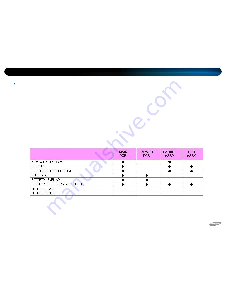
You have to make adjustments for each feature after replacing an electronic item in the PL70.
The following table represents necessary adjustments for each item replacement.
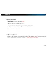
2. Adjustment
Basic Information of Adjustment
Adjustment Caution
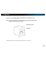
1. Adjust for each feature after replacing an electronic item, referring to the following table.
Summary of Contents for PL70
Page 1: ...Technical Information Samsung camera samsung PL70 SAMSUNG...
Page 2: ...Contents Part 1 Firmware Part 2 Adjustment Part 3 Disassembly...
Page 4: ...1 Firmware Checking Firmware Initialization 1 Turn on the Camera...
Page 5: ...1 Firmware 2 Press and hold the WIDE Down and then press the Power OFF...
Page 6: ...1 Firmware 3 Turn on the camera and check whether the camera is reset or not...
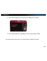
Page 8: ...1 Firmware 4 After checking Firmware version turn off the camera...
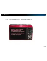
Page 16: ...1 Firmware 4 F W ver which will be upgraded is shown on LCD automatically...
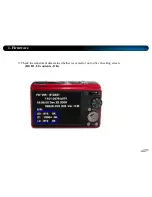
Page 19: ...1 Firmware 7 Press the SHUTTER S1 Button then back up process will be done...
Page 20: ...1 Firmware 8 After completed the Back up process comes out to Power Off status...
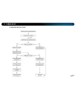
Page 25: ...4 Adjustment Flow Chart 2 Adjustment...
Page 50: ...3 Disassembly Disassemble Camera Procedure of disassembly 1 Remove 2 screws...
Page 51: ...3 Disassembly 2 Remove 2 screws...
Page 52: ...3 Disassembly 3 Remove 2 screws...
Page 53: ...3 Disassembly 4 Separate the FRONT COVER ASSY...
Page 54: ...3 Disassembly 5 Separate the BACK COVER ASSY...
Page 55: ...3 Disassembly 6 Separate the SIDE COVER ASSY...
Page 57: ...3 Disassembly 8 Separate the BARREL ASSY...
Page 58: ...3 Disassembly 9 Separate the BUTTON PCB ASSY from the connector...
Page 59: ...3 Disassembly 10 Remove the screws on BUTTON PCB ASSY Give attention to bottom side of PCB...
Page 60: ...3 Disassembly 11 Separate the BUTTON PCB ASSY...
Page 61: ...3 Disassembly 12 Separate the LCD ASSY PCB from connector...
Page 62: ...3 Disassembly 13 Separate the LCD ASSY...
Page 64: ...3 Disassembly 15 Separate the MAIN PCB ASSY...
Page 65: ...3 Disassembly 16 Remove the screws on FLASH PCB ASSY Give attention to left side of PCB...
Page 66: ...3 Disassembly 17 Separate the FLASH PCB ASSY...
Page 67: ...3 Disassembly Disassemble Barrel 1 Remove 3 screws for the CCD PCB ASSY...
Page 68: ...3 Disassembly 2 Separate the CCD PCB ASSY...
Page 69: ...3 Disassembly 3 Separate the Shutter PCB Connector...
Page 70: ...3 Disassembly 4 Remove 2 screws on MOTOR ASSY...
Page 71: ...3 Disassembly 5 Remove 3 screws on LENS BASE ASSY...
Page 72: ...3 Disassembly 6 Separate the LENS BASE ASSY...
Page 73: ...3 Disassembly 7 Separate the ZOOM GEAR...
Page 74: ...3 Disassembly 8 Separate the SHUTTER ASSY PCB...
Page 75: ...3 Disassembly 9 Separate the CAM BARRELASSY from OUTER CAM BARREL...
Page 76: ...3 Disassembly 10 Separate the CAM BARREL ASSY...
Page 77: ...3 Disassembly 11 Separate the INNER CAM BARREL ASSY from GUIDE BARREL...
Page 78: ...3 Disassembly 12 Take apart INNER CAM BARREL ASSY...
Page 79: ...3 Disassembly 13 Separate the 2ND 3RD BARRELASSY from INNER CAM BARREL...
Page 80: ...3 Disassembly 14 Take apart 2ND 3RD BARREL ASSY...
Page 81: ...3 Disassembly 15 Separate the SHUTTER ASSY from 2ND 3RD BARREL ASSY...
Page 82: ...3 Disassembly 16 Take aparat 2ND 3RD BARREL from ZOOM RING...
Page 83: ...3 Disassembly 17 Take apart 2ND 3RD BARREL...
Page 84: ...3 Disassembly 18 Separate the 2ND 3RD BARREL from LENS CAP ASSY...
Page 85: ...3 Disassembly 19 Take apart LENS CAP ASSY...
Page 87: ...3 Disassembly 2 Caution for the ZOOM RING 2ND 3RD BARREL ASSY Should be matched with C D c d...
Page 88: ...3 Disassembly 3 Assemble the ZOOM RING ASSY...
Page 89: ...3 Disassembly 4 Caution for the SHUTTER ASSY Should be matched with B b...
Page 90: ...3 Disassembly 5 Should be matched with E F e f...
Page 91: ...3 Disassembly 6 Assemble INNER CAM BARREL ASSY...
Page 93: ...3 Disassembly 8 Assemble the CAM BARRELASSY...
Page 94: ...3 Disassembly 9 Caution for the OUTER CAM BARREL CAM BARRELASSY Should be matched each points...
Page 95: ...3 Disassembly 10 Assemble the OUTER CAM BARRELASSY...
Page 96: ...Thank you...


