'LVDVVHPEO\DQG5HDVVHPEO\
3DUWV
([SODQDWLRQ3KRWR
([SODQDWLRQ
3DUWV
([SODQDWLRQ3KRWR
([SODQDWLRQ
$WWHQWLRQ
7KH&HUDPLF*ODVVPD\EUHDNLI\RXXVHIRUFHHVSHFLDOO\RQWKHHGJH
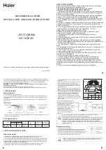
Ceramic Glass
1. Disconnect power.
ceramic glass with the radiator board.
2. Remove 12 screws from 4 edges (3
4. After replacing the ceramic glass, lock
the ceramic glass to the radiator
board by screws.
1.Lift up the display board.(The
display board is fixed by 4
plastic buckle)
2. Disconnect all sub-wire.
3. Replace the display board.
Display board
3
Ͳ
1
Replacement
of
the
Ceramic
Glass
3
Ͳ
2
Replacement
of
the
Display
board
up
A
B
1
2
C
D
3.Use the shape "-" group to lift
the ceramic glass from the radiator
board at the points shown in
image 1 (A) with the height shown
in image 2 (lift until screw holes are
above the radiator board). After
taking the same operations at points
(B), (C) and (D) shown in image 1,
the ceramic glass will be able to be
removed from the radiator board.
screws each edge) that are locking the


