


2
_ Before you begin
before you begin
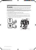
ANTI-TIP DEVICE
WARNING:
To reduce the risk of tipping the appliance, the appliance must be
secured by properly installed anti-tip devices packed with the appliance.
a)
A child or adult can tip the range and be killed.
b)
Install the anti-tip device to the structure and/or the range at rear right (or rear left)
of the range bottom.
c)
Engage the range to the anti-tip device by leveling leg at rear right (or rear left) of
the range bottom.
d)
Re-engage the anti-tip device if the range is moved.
e)
See installation instructions for details.
f)
Failure to do so can result in death or serious burns to children or adults.
AbouT ThIs mANuAl
READ THESE INSTRUCTIONS COMPLETELY AND CAREFULLY.
Important note to the installer
• Read all instructions contained in these installation instructions before installing range.
• Remove all packing materials from the oven compartments before connecting the electrical supply
to the range.
• Observe all governing codes and ordinances.
• Be sure to leave these instructions with the consumer.
Important note to the consumer
Keep these instructions for the local electrical inspector’s use.
• As when using any appliance generating heat, there are certain safety precautions you should follow.
• Be sure your range is installed and grounded properly by a qualified installer or service technician.
• Make sure the wall coverings around the range can withstand the heat generated by the range.
• To eliminate the need to reach over the surface elements, cabinet storage space above the elements
should be avoided.
• The range should not be placed on a base.
FoR YouR sAFETY
WARNING
WARNING
If the information in this manual is not followed exactly, a fire or electrical
shock may result causing property damage, personal injury or death.
WARNING
WARNING
Before beginning the installation, switch power off at the service panel and
lock the service disconnecting means to prevent power from being switched on accidentally. When the
service disconnecting means cannot be locked, securely fasten a prominent warning device, such as a
tag, to the service panel.
WARNING
WARNING
This appliance must be properly grounded.
WARNING
Installation-USA DG68-00108G-01_EN.indd 2
2012-02-16 �� 11:14:21


