background image

18

3. Disassembly and Reassembly

3-10 Removing Lamp

WARNING

Disconnect power before servicing the range. Replace all panels before operating range. Failure to do so 
can result in death or electrical shock.

CAUTION

When you work on the electric range, be careful when handling the sheet metal parts. Sharp edges may be 
present, and you can cut yourself if you are not careful.

Parts

Explanation Photo

Lamp

Explanation

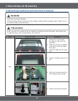
1.

Disconnect power.

2.

Remove oven door.

3.

Turn the glass bulb cover in the oven counterclockwise to remove.

4.

Turn bulb counterclockwise to remove from socket.

5.

Replace bulb and cover by turning clockwise.

CAUTION

Be careful not to scratch or chip the oven liner paint when to remove the oven light socket 
in the next step.

Explanation Photo

Explanation

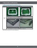
To replace socket assembly:

6.

Disconnect the wires from the socket 
terminals.

7.

Use a screwdriver and bend the clips 
on the socket away from the edges of 
the liner hole(there are 6 clips on th 
e socket), and pull the socket out of 
the liner. Push the socket out from the 
rear of the unit.

* Reassembly of All part is the reverse order of disassembly.

Summary of Contents for NE58F9710WS

Page 1: ...e GSPN see rear cover for the more information 1 Precaution 3 Disassembly and Reassembly 4 Troubleshooting 5 PCB Diagrams 6 Wiring Diagram SLIDE IN RANGE FREESTANDINGRANGE BASIC NE58F9710WS MODEL NE58...

Page 2: ...nd The Ceramic Glass Cooktop 13 3 6 Removing The Latch Door Switch Door Plunger 14 3 7 Removing Heater Broil 15 3 8 Removing Heater Bake 16 3 9 Removing Convection Element Fan Convection and Motor Con...

Page 3: ...s situations If you need repairs contact a SAMSUNG Service Center or your dealer I WKH SRZHU FRUG LV GHIHFWLYH LW PXVW EH UHSODFHG E D TXDOL HG VHUYLFH DJHQW ZLWK D 8 OLVWHG UDQJH FRUG OHFWULFDO OHDGV...

Page 4: ...elements or interior VXUIDFHV RI RYHQ XQWLO WKH KDYH KDG VXI FLHQW time to cool Other surfaces of the appliance may become hot enough to cause burns among these surfaces are oven vent openings and su...

Page 5: ...keep pet birds in the kitchen the health of birds is extremely sensitive to the fumes released during an oven self clean cycle Fumes may be harmful or fatal to birds Move birds to well ventilated room...

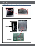
Page 6: ...Precaution 1 4 Model Serial Number Label and Tech Sheet Locations 7KLV 0RGHO 6HULDO 1XPEHU ODEHO DQG 7HFK 6KHHW ORFDWLRQV DUH VKRZQ EHORZ Tech Sheet Location On Low Rear Cover Model Serial Number Loca...

Page 7: ...m Clean How to Use Pour the water 10oz detergent Push the steam cleaning button IWHU QLVKHG VWHDP FOHDQ IHDWXUH WKH RYHQ ZLOO EH shut off automatically in half a minute Wipe it out with wet cloths Ope...

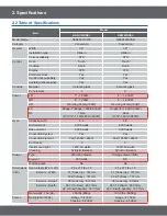
Page 8: ...F ULGJH ULGJH XDO RF Triple Dual Oven Capacity cu ft 5 8 5 8 Broil element 4 200 watts 4 200 watts Bake element 3 000 watts 3 000 watts Convection System Yes Yes Convection element HV 9 HV 9 of Racks...

Page 9: ...9 6SHFL FDWLRQV 2 3 Accessory Item Description Code No Q ty RACK FLAT DG75 01001C 2 SENSOR PROBE DG32 00013A 1 RACK WIRE BOTTOM DG75 01056A 1...

Page 10: ...emove the 9 screws from the Cover Back Main Wire and remove the panel Reassembly of All part is the reverse order of disassembly 3 1 Removing the Assy Frame Cooktop Item How to use Pictures Screw driv...

Page 11: ...be careful when handling the sheet metal parts Sharp edges may be present and you can cut yourself if you are not careful Parts Explanation Photo Explanation PCB Main PCB Main 1 Turn off the electrica...

Page 12: ...k on the electric range be careful when handling the sheet metal parts Sharp edges may be present and you can cut yourself if you are not careful Parts Explanation Photo Explanation Touch PCB 1 Turn o...

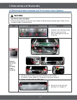
Page 13: ...r electrical shock Parts Explanation Photo Explanation Surface elements and Ceramic Glass Cooktop 1 Unplug the cord or disconnect power 2 Open oven door and remove the 4 screws located at under the Co...

Page 14: ...Latch Door Switch Door Plunger 1 Turn off the electrical supply going to the range 2 Open the oven door 3 Raise the cooktop see page 14 for the procedure 4 To remove the Latch Door a Remove the 2 scre...

Page 15: ...arp edges may be present and you can cut yourself if you are not careful Parts Explanation Photo Explanation Broil 1 Turn off the electrical supply going to the range 2 Open the oven door and remove t...

Page 16: ...of the unit 3 Remove Cover Back Main Wire See step 3 4 on page 10 for procedure Remove terminal block and bracket cover access by unscrewing the three screws Disconnect the two wires from the warming...

Page 17: ...Main Wire from the unit See step 3 on page 10 for procedure 4 Remove oven door See Page 29 on page for procedure 5 Unscrew 2 screws and remove Cover Casing 6 Unscrew 2 screws and remove Bracket Convec...

Page 18: ...urn the glass bulb cover in the oven counterclockwise to remove 4 Turn bulb counterclockwise to remove from socket 5 Replace bulb and cover by turning clockwise CAUTION Be careful not to scratch or ch...

Page 19: ...g the sheet metal parts Sharp edges may be present and you can cut yourself if you are not careful Parts Explanation Photo Explanation Sensor Thermistor Lower Sensor 1 Turn off the electrical supply g...

Page 20: ...he electric range be careful when handling the sheet metal parts Sharp edges may be present and you can cut yourself if you are not careful Parts Explanation Photo Assy Drawer Heater Warming Drawer Ex...

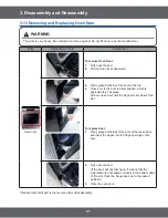
Page 21: ...4 Close door to the door removal position which is approximately 5 degrees Lift door up and out until the hinge arm are clear of the slot To replace door 1 Firmly grasp both sides of the door at the...

Page 22: ...c range be careful when handling the sheet metal parts Sharp edges may be present and you can cut yourself if you are not careful Parts Explanation Photo Explanation Door 1 Remove the oven door from t...

Page 23: ...Explanation Photo Explanation Handle Door To remove Handle Door 1 Remove 2 screws to remove Handle Door Glass Inner To remove Glass Inner 1 Remove 6screws from rear side of door to remove 2 Hinge Doo...

Page 24: ...lass Inner Parts Explanation Photo Handle Door Explanation 4 5HPRYH DI H RRU DQG WDNH RXW WKH ODVV QQHU DVVHPEO Explanation Photo Explanation 5 8QIROG DQJHV RI RYHU UDPH QQHU ODVV WR WDNLQJ RXW ODVV Q...

Page 25: ...urself if you are not careful Parts Explanation Photo Gasket door Explanation 1 Open the oven door to its fully down position 2 Pull the ends of the gasket out of the liner holes 3 Pull the oven door...

Page 26: ...u can cut yourself if you are not careful Parts Explanation Photo Explanation Panel Side Panel Side 1 Turn off the electrical supply 2 Remove the oven door from the range see page 3 15 for the procedu...

Page 27: ...eck the resistance of the each heater 3 Check whether DLB of Main PCB Broil Bake and Convection heater relay are being worked normally 4 Check whether there is any disconnection of harness which is li...

Page 28: ...ation error 1 Check whether connector TE201 of SUB PCB has been inserted 2 If there is not a problem occurred with connector on Sub PCB and Touch glass replace the Control box SE Key short 1 Check whe...

Page 29: ...VHQVRU DQG 1R 1 RI PDLQ 3 0HDVXUH UHVLVWDQFH RI FRQQHFWRU 1 RI 0DLQ 3 1RPDO 0DNH VXUH WKH SDWWHUQ VROGHULQJ GDPDJHG SDUWV UHODWHG WR RYHQ VHQVRU RI PDLQ 3 DQG UHSDLU WKHP RU UHSODFH PDLQ 3 DFFRUGLQJ...

Page 30: ...he connecting condition of harness related with oven sensor Check connector and harness connected to main PCB Check whether harness on connector 1 RI PDLQ 3 LV FRQQHFWHG QRPDOO LQWR WKH FRQQHFWRU 1 RU...

Page 31: ...whether voltage AC 120V is offered to lock motor with letting lock work or not Ok Ok No No Repair damaged harness or replace Check whether harness connected normally into CN501 of main PCB Measure re...

Page 32: ...n Sub PCB Main PCB have a short circuit Ok Ok Ok No No No With replacing Sub PCB and make set work Repair damaged harness or replace END END END Replace Sub PCB Main PCB END Repair the area of circuit...

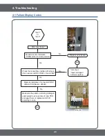
Page 33: ...roubleshooting tE Disconnect power Get rid of connector TE201 on Sub PCB Check connected normally into Touch glass TE201 on Sub PCB Repair damaged wire or replace END Sub PCB TE201 4 1 Failure Display...

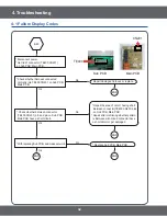
Page 34: ...her between keypad and cable have a short circuit Ok Ok No No Replace Control PCB Touch Control PCB Glass Repair the area of circuit having short between connector TE201 pins on Sub PCB Repair after c...

Page 35: ...Check whether harness connected normally into CN401 of main PCB 0HDVXUH UHVLVWDQFH RI 0HDW SUREH Measure resistance CN401 of main PCB pin 6 pin 7 10 11 END Ok No No No Ok Ok Replace Meat probe Replac...

Page 36: ...36 4 Troubleshooting Control PCB Operation Sort of Control PCB Main PCB Front Back Sub PCB Front Back Front...

Page 37: ...switch upper lamp and relay of upper convection fan connected CN502 This connector which have lower lamp and relay of lower convection fan connected RY Source Relay RY501 7KLV LV UHOD ZKLFK FRQWURO VR...

Page 38: ...r which is connected with Main PCB to communicate CN400 When do micom revision connect to micom writer No connection at normal times CN200 When do micom revision connect to micom writer No connection...

Page 39: ...serted into relay on sub PCB or not take action follow as Replace or repair harness Replace or repair sub PCB Measure resistance both ends of terminal on thermostat normal 0 ohoms Check whether harnes...

Page 40: ...e on touch PCB is in normal state 5HSODFH DIWHU FRQ UPLQJ ZKHWKHU LW KDV been loosen or disconnected Make sure connector CN07 on main PCB or PCB pattern 5HSODFH RU UHSDLU DIWHU FRQ UPLQJ ZKHWKHU keypa...

Page 41: ...ce or repair connector Replace sub PCB It has smell or smoke when oven has been started initially This is in normal state It has smell or smoke with burning dirt in oven or a foreign substance when ov...

Page 42: ...k connections Check the circuit breaker Replace or Repair the wiring Troubleshooting Heating Check the relay terminal voltage 240V Heating Failure Check the wiring Check the all IGBT terminal resistan...

Page 43: ...12V Check the Assy Inverter Module Assy Touch PCB s input voltage 5V 12V GND Reset the circuit braker or check main power Repair Faulty wiring or PCB check Check Terminal block voltage 240V Repair the...

Page 44: ...ce values of KHDWHU V WHUPLQDO DIWHU WDNLQJ RII harness from heater 0HDVXUH YROWDJH RI KHDWHU V WHUPLQDO after making oven work by pressing bake keypad Make sure that voltage has to be measured for mo...

Page 45: ...r and removing lamp Measure the voltage at the lamp sockets terminal after turning on the Lamp by pressing the Oven light on the main keypad Approx Terminal voltage of lamp socket 120V Replace or repa...

Page 46: ...witch Make sure whether wire housing and terminal is connected with switch has been damaged or not 1RPDO RSHQ Nomal close Replace or repair if wire or terminal has been damaged Check whether the resis...

Page 47: ...45 1170 17 14 10 961 86 122 50 1188 93 23 5 980 95 212 100 1374 93 32 0 1000 00 302 150 1558 01 41 5 1019 02 392 200 1738 06 50 10 1038 02 482 250 1915 39 59 15 1056 99 572 300 2089 69 68 20 1075 92 6...

Page 48: ...d with Oven Fan Low 12 RY512 Oven Lamp L Relay This is relay which is connected with Oven Lamp Low 13 CN101 Power Connector This is to supply power with SMPS 14 CN201 Sub Communication Connector This...

Page 49: ...ng s authorization No Parts Number Part Name Function and Rule 1 TE400 Main Communication Connector This is connector which is connected with Main PCB to communicate 2 CN200 On Board Writing Connector...

Page 50: ...50 6 Wiring diagram 6 Wiring diagram 6 1 Wiring diagram This Document can not be used without Samsung s authorization...

Page 51: ...2013 Printed in Korea GSPN GLOBAL SERVICE PARTNER NETWORK Area Web Site Europe CIS Mideast Africa gspn1 samsungcsportal com Asia gspn2 samsungcsportal com North Latin America gspn3 samsungcsportal co...

Reviews: