


E-
14
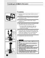
Installation
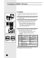
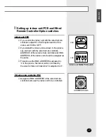
Open the wired remote controller using the 2 grooves
on the top.
1
Secure the rear cover of the wired remote controller on
the wall with 2 screws.
2
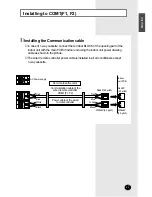
Connect the indoor unit housing with the wired remote
controller housing or connect the F3, F4 terminal of the
wired remote controller to the F3, F4 terminal of the
terminal block depending on the indoor unit type.
5
Reassemble the wired remote controller.
6
Connect V1, V2 with the wired remote controller
terminal V1, V2.
3
After checking the kind of outdoor unit, assign the DS01
switch SW2 of the indoor unit PCB to ‘OFF’.
4
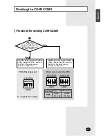
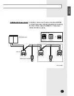
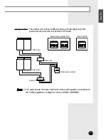
◆
If you set to COM1 and install it to COM2, ‘EA’
communication error sign is displayed on the
wired remote controller.
C
C
C
C
A
A
A
A
U
U
U
U
T
T
T
T
II
II
O
O
O
O
N
N
N
N
◆
Install the wired remote controller of GHP in the same
way.
◆
The wired remote controller must be installed by an
installation specialist.
◆
Before installing the wired remote controller, check
that you have turned off the main power.
◆
All cables should be installed according to the national
wiring rules and you must install it to the wall not to
be touched by users.
◆
Communication cable and power cable should be
installed separately. (The wired remote controller can
be operated abnormally due to electric trouble.)
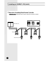
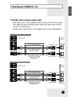
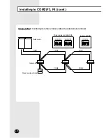
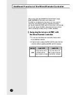
Installing to COM2(F3, F4) (cont.)
Housing
Tighten the
cable with the
wire joint
(accessories)
tightly.
Indoor unit
Wired
remote
controller
Cables
(purchased
on the spot)
F3
F4
Indoor unit
Wired
remote
controller
Cables
(purchased
on the spot)
Summary of Contents for MWR-TH00
Page 33: ...E 33 ENGLISH Memo ...


