background image

E-

3


Contents

   W

IRED

 R

EMOTE

 C

ONTROL


AND

 A

CCESSORIES

  ........................................ 4




Accessories  ............................................................................................... 4

   I

NSTALLING


THE

 W

IRED

 R

EMOTE

 C

ONTROL

  ............................................. 5




Installation  ................................................................................................ 5 




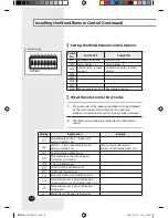
Setting the Wired Remote Control Options  ............................. 6 




Wired Remote Control Error Codes  .............................................. 6 




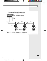
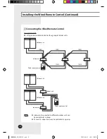
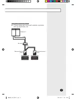
Connecting the Wired Remote Control  ..................................... 7

Note


The illustrations will help you to understand the 
symbols displayed in the pictures.


The illustrations in the step-by-step procedures use 
3 different symbols:

PRESS

PUSH

HOLD DOWN

MWR-SH00_IM_E_28133.indd   3

2007-06-21   ソタタ・10:48:35

Summary of Contents for MWR-SH00

Page 1: ...INSTALLATION MANUAL WiredRemoteControl MWR SH00 System Air Conditioner DB98 28133A 1 E MWR SH00_IM_E_28133 indd 13 2007 06 21 10 49 11...

Page 2: ...ol consult an authorized installation center WARNING CAUTION Do not use inflammable gases near the wired remote control Do not install the wired remote control in a location where it will come into co...

Page 3: ...ired Remote Control Options 6 Wired Remote Control Error Codes 6 Connecting theWired Remote Control 7 Note The illustrations will help you to understand the symbols displayed in the pictures The illus...

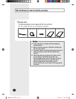
Page 4: ...n cable and the power cable to avoid malfunction of the unit Connecting the power cable to the communication terminal of the wired remote control will cause serious damage to the wired remote control...

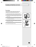
Page 5: ...p 2 Secure the rear cover of the wired remote control to the wall with 2 screws 3 Connect the V1 V2 terminal of the wired remote control to the V1 V2 terminal of the ventilator 4 Connect the F3 F4 ter...

Page 6: ...als for the error codes reference 2 The following error codes are related to the wired remote control Display Explanation Remark Wired remote control Indoor unit communication error Master Slave wired...

Page 7: ...vidual Control Using one wired remote control for one indoor unit Note The wired remote control can be only installed on COM2 Outdoor unit Indoor unit COM1 COM2 COM1 COM2 COM2 Wired remote control MWR...

Page 8: ...16 indoor units may be controlled as a group Group Control Using one wired remote control for a group of indoor units Outdoor unit Indoor unit COM1 COM1 Wired remote control COM2 COM2 COM1 Outdoor uni...

Page 9: ...2 wired remote controls can be used to control a single indoor unit or a group of indoor units Outdoor unit Indoor unit COM1 Wired remote control Master COM2 Wired remote control Slave MWR SH00_IM_E_...

Page 10: ...E 10 MEMO MWR SH00_IM_E_28133 indd 10 2007 06 21 10 49 10...

Page 11: ...E 11 MWR SH00_IM_E_28133 indd 11 2007 06 21 10 49 10...

Page 12: ...MWR SH00_IM_E_28133 indd 12 2007 06 21 10 49 10...

Reviews: