


4-2-2 Test Mode
The test mode is used to test certain functions of the
machine. The available tests are:
•User mode : Clean drum
→
Adjust shading
→
Notify toner low
•Tech mode : Switch Test
→
Modem Test
→
Memory Test
→
ROM Test
→
DRAM Test
→
Pattern Test
To enter the Test Mode:
1. Get into the Tech mode by pressing
Menu
,
#
,
1
,
9
,
3
,
4
.
2. In Tech mode, press
Menu
, and ‘
Maintenance
’
on the one-touch keypad.
3. Scroll to the options by pressing or repeatedly
until you find the one you want.
4. Press
Enter
to initiate the test mode.
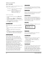
CLEANING DRUM
This procedure removes excess toner on the OPC
drum.
1. Make sure that paper is loaded in the automatic
feeder.
2. Press Menu, and Self-Test on the one-touch
keypad.
3. Press Enter. The machine automatically pulls in a
sheet of paper, and prints out. The toner particles
on the OPC drum surface is fixed to the paper.
ADJUST SHADING
This procedure is needed to set (make) a new
shading reference value. The reference value is
preset at factory. However, when the CIS or the
main board is replaced with new one, the reference
value must be set again.
Load the white, letter-sized paper into the feeder
and perform the test mode (MENU+ONE-TOUCH
‘SYSTEM SETUP’). Follow the next steps as
instructed through the LCD window. After the
shading value is newly set, the shading value
pattern is automatically printed. The shading value
pattern shows the value of the white reference level
of the Contact Image Sensor. Check for the
waveform in the pattern. It is best when the wave
form is level. If there are many points sharply
broken, perform the Make shading procedure
several times until you get a level waveform.
SWITCH TEST
This test checks the operation of the LCD display
and the LED indicators that interface the switches
on the operation panel.
MODEM TEST
This test causes the machine to generate a particular
frequency to verify the operation of the modem
control circuits and the modem.
MEMORY TEST
This test is used for checking the Random Access
Memory (RAM) on the main PBA. If all memory is
working normally, the LCD shows TESTING OK!.
When this testing is carried out, any picture data
stored in memory is erased.
ROM TEST
This test mode will display and check the current
ROM level in your machine.
DRAM TEST
This test checks the DRAM memory status and
shows if it is functioning properly
PATTERN TEST
1. Pattern Test ?
2. Pattern 1 ? - There are 4 different pattern tests.
Scroll to the options by pressing
or
repeatedly until you find the one you want.
3. Press START key.
4. Key in the number of pages.
5. Press START key.
Notify Toner Low
With this feature enabled, when the toner becomes
low, the toner low information will be sent to ta
specified contact point, for example, the service
company. After you access this menu, select ON,
and when the LCD prompts, enter the name and the
number of the contact point, the customer’s fax
number, the model name, and the serial number.
4-4
Samsung Electronics
Maintenance & Troubleshooting
FLASH VER. : 1.0.0 V
ENGINE VER : 1.0.0 V
Summary of Contents for Msys 6800
Page 10: ...2 6 Samsung Electronics Specification Memo ...
Page 58: ...4 28 Samsung Electronics Maintenance Troubleshooting MEMO ...
Page 81: ...5 22 Samsung Electronics Exploded Views and Parts Lists MEMO ...
Page 95: ...MEMO Samsung Electronics 8 2 ...
Page 96: ...PCB Diagrams Samsung Electronics 9 1 9 1 Main PCB Diagram Top 9 PCB Diagrams ...
Page 97: ...PCB Diagrams Samsung Electronics 9 2 9 2 Main PCB Diagram Bottom ...
Page 98: ...PCB Diagrams Samsung Electronics 9 3 9 3 LIU PCB Diagram Top 9 4 LIU PCB Diagram Bottom ...
Page 99: ...PCB Diagrams Samsung Electronics 9 4 9 5 Engine PCB Diagram Top ...
Page 100: ...PCB Diagrams Samsung Electronics 9 5 Engine PCB Diagram Top ...
Page 101: ...PCB Diagrams Samsung Electronics 9 6 9 6 Engine PCB Diagram Bottom ...
Page 102: ...PCB Diagrams Samsung Electronics 9 7 Engine PCB Diagram Bottom ...
Page 103: ...PCB Diagrams Samsung Electronics 9 8 9 7 OPE PCB Diagram ...
Page 104: ...PCB Diagrams Samsung Electronics 9 9 OPE PCB Diagram ...
Page 105: ...PCB Diagrams Samsung Electronics 9 10 MEMO ...
Page 106: ...Connection diagram Samsung Electronics 8 1 8 Connection diagram ...
Page 107: ...MEMO Samsung Electronics 8 2 ...
Page 110: ...Main Circuit Diagram 3 5 Samsung Electronics 10 3 Schematic Diagrams ...
Page 111: ...Schematic Diagrams 10 4 Samsung Electronics Main Circuit Diagram 4 5 ...
Page 113: ...Schematic Diagrams 10 6 Samsung Electronics 10 2 Engine Circuit Diagram 1 4 ...
Page 114: ...Engine Circuit Diagram 2 4 Samsung Electronics 10 7 Schematic Diagrams ...
Page 115: ...Schematic Diagrams 10 8 Samsung Electronics Engine Circuit Diagram 3 4 ...
Page 116: ...Engine Circuit Diagram 4 4 Samsung Electronics 10 9 Schematic Diagrams ...
Page 117: ...Schematic Diagrams 10 10 Samsung Electronics 10 3 LIU Circuit Diagram ...


