background image

4.  Maintenance & Troubleshooting

4-1  Preventative Maintenance

The cycle period outlined below is a general guideline for maintenance. The example list is for an average
usage of 50 transmitted and received documents per day. Environmental conditions and actual use will vary
these factors. The cycle period given below is for reference only.

Samsung Electronics

4-1

COMPONENT

CLEANING CYCLE

REPLACEMENT CYCLE

SOLUTION

SCANNER

PRINTER

ADF Rubber

ADF Roller

Drive Roller

White Roller

CIS

Cartridge

Pickup Roller

Feed Roller

Transfer Roller

Fuser

6 Months

1 Year

1 Year

6 Months

6 Months

1 Year

1 Year

10,000 Pages

20,000 Pages

50,000 Pages

50,000 Pages

6,000 Pages

50,000 Pages

50,000 Pages

50,000 Pages

30,000 Pages

4-2  Diagnostics

This section describes methods and procedures to isolate the cause of a malfunction in the machine. This
machine displays diagnostic information on the LCD. In addition, it can perform a series of tests that allow the
machine to observe individual machine functions.

4-2-1   Error Messages

Error Message

Description 

Solution

RETRY REDIAL?

The machine is waiting the programmed 

You can press START to immediately 

interval to automatically redial. 

redial, or STOP to cancel the redial 
operation.

COMM. ERROR

A problem with the facsimile 

Try again.

communications has occurred.

DOCUMENT JAM

Loaded document has Jammed 

Clear the document Jam.

in the feeder

Summary of Contents for Msys 6750

Page 1: ...50 SF 6800 Manual FACSIMILE CONTENTS 1 Precautions 2 Specifications 3 Disassembly and Reassembly 4 Troubleshooting 5 Exploded Views and Parts List 6 Electrical Parts List 7 Block Diagram 8 Connection Diagram 9 PCB Diagrams 10 Schematic Diagrams ...

Page 2: ...ELECTRONICS Samsung Electronics Co Ltd December 1999 Printed in Korea VERSION NO 2 00 P N JC81 00285A ...

Page 3: ...al safety related characteristics which might not be obvious from visual inspection These safety features and the protection they provide could be lost if a replacement component differs from the original This holds true even though the replacement may be rated for higher voltage wattage etc Components critical for safety are indicated in the parts list with symbols Use only replacement components...

Page 4: ...val devices not classified as anti static can generate electrical charges sufficient to damage ESDs 5 Do not use Freon propelled chemicals When sprayed these can generate electrical charges sufficient to damage ESDs 6 Do not remove a replacement ESD from its protective packaging until immediately before installing it Most replacement ESDs are packaged with all leads shorted together by conductive ...

Page 5: ...ed 8 PPM Letter size Automatic document feeder 50 pages 75g m 2 20lb 0 09 0 10 mm thickness Documents size Width 148 to 216 mm Length 128 to 1500mm Single Page STA 356 mm LGS Size Finr 1500 mm S fine 1500mm 279 to 297mm Multi Pages Weight 50 to 100 g m 2 Single Page 50 to 90 g m 2 20 Pages 75 g m 2 40 Pages One touch dial 20 locations LCD 16 characters x 2 lines 2 2 SCANNER Scanning Method Sheet f...

Page 6: ...8 356mm Width 98 216mm Weight For MPF 60 90g m 2 For Manual 60 120g m 2 Paper Capacity MPF 250 Sheets based on 75g m 2 Manual Slot 1 Sheet Paper Stacker Capacity Face up 150 Sheets 75g m 2 20 lb Warming up Time About 20 sec First Printing Time Stand By About 25 sec Power Save Mode About 40 sec Power Rating AC 110V 127V 15 50 60Hz 3Hz AC 220V 240V 15 50 60Hz 3Hz Power Consumption Max 210Wh Stand by...

Page 7: ...0 95 RH Weight SET Net 9 kg SCF Gross 14 3 kg Net 4 8 kg Gross 6 0 kg External Dimension 386 W X 405 D x 270 H mm Developer Life Span 5 Pattern Min 6 000 Sheets Developing Non magnetic Contact Developing Charging Conductive Roller Charging Density Adjustment Dark Medium Toner Supply Method Exchanging Toner Cartridge New Developer Checkable Transfer System Pre transfer By LED Conductive Roller Tran...

Page 8: ... 16mm 10 Sheets 75g m2 Paper After Cooling Less than 16mm 10 Sheets 75g m2 Paper Reliability Insulation Resistance Less than 10 MΩ at DC 500V Dielectric Strength AC 1000V DC 1420V 10mA Ground Continuous Less than 0 1Ω Voltage DIP Rated Voltage 15 AC Impulse Noise AC 1000V 10 100 200 400 1000ns Rated Power Leakage Current Less than 3 5mA Surge 6 KV 500A OZONE Emission Less than 0 1 ppm 8 Hours Top ...

Page 9: ...t 2 5Amps 3Amps Max Inrush Current 40 Ap p at 25 C 40 Ap p at 25 C Output DC Line Regulation 24V 10 12V 5 Road Regulation 12V 5 5V 5 Ripple Noise 24V Peak 500mVp p 12V Peak 500mVp p 12V Peak 500mVp p 5V Peak 300mVp p Over Current Protect 24V 2 7A 10 by Circuit 5V 3A 10 by Circuit Over Voltage Protect 24V 33V 5V 5 6V Samsung Electronics 2 5 Specification ...

Page 10: ...2 6 Samsung Electronics Specification Memo ...

Page 11: ... that will be affected Whenever servicing the machine you must perform as follows 1 Check to verify that documents are not stored in memory 2 Be sure to remove the toner cartridge before you disassemble parts 3 Unplug the power cord 4 Use a flat and clean surface 5 Replace only with authorized components 6 Do not force plastic material components 7 Make sure all components are in their proper posi...

Page 12: ...roller is heavily worn replace it with a new one 2 Push the bushing on the both ends of the roller slightly inward then rotate it until it reaches the slot Then lift the roller out Bushing 3 4 Transfer Roller 1 Open the front cover and release one end of the roller using a proper tool as shown in the square 2 Pull the other end of the roller slightly inward then lift it up Transfer roller Samsung ...

Page 13: ...hen remove the rear cover 2 If you want to remove the dummy fan from the rear cover remove two screws and release two latches then take it out 3 6 Left Side Cover 1 Before you remove the cover you should remove Rear cover see page above 2 Open the front cover remove one screw then remove the left side cover ...

Page 14: ...e front cover and remove one screw 4 Unplug the speaker harness from the main board then remove the right side cover 3 Remove three screws then pull the plate slightly toward you to release the side cover 5 If you remove the fan from the side cover remove two screws then take it out When you reassemble the fan make sure that the fan is placed correctly ...

Page 15: ...t side covers see page 3 3 3 4 2 Open the OPE panel then set the support OPE to the OPE panel 3 From the right side of the main body remove two ground screws and unplug one OPE harness 4 To unlatch the OPE ass y spread the both ends of the OPE ass y shown in circles in the figure below then remove the OPE ass y Spread the both ends of the OPE ass y ...

Page 16: ...F rubber push the plastic latches on the ADF rubber from the bottom of the OPE ass y Then remove the ADF rubber 2 Remove a screw and release one of the latches securing the LCD board then remove the OPE board with the LCD board OPE PBA on the OPE Ass y 1 Remove seven screws release the plastic latches securing the board then turn the board upside down ...

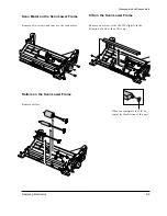
Page 17: ...ver sensor and lift it up 3 7 Samsung Electronics Pinch Spring on the OPE Ass y Remove three screws securing the pinch spring then take it out Spring on the OPE Ass y Release one end of the spring and take it out from the OPE ass y Pinch on the OPE Ass y Remove the pinch from the OPE ass y ...

Page 18: ...e 3 3 3 4 Top Assembly see page above 2 Remove four screws and remove the scan lower frame 1 2 3 3 9 Top Assembly 1 Before you remove the cover you should remove Rear cover see page 3 3 Left Right side covers see page 3 3 3 4 OPE ass y see page 4 8 2 Remove two screws and unplug two connectors from the main board then remove the Top ass y pushing in the direction of the arrows in order ...

Page 19: ...er Frame Remove two screws and remove the scan motor Rollers on the Scan Lower Frame Remove rollers CIS on the Scan Lower Frame Remove one screw slide the CIS slightly in the direction of arrow then lift it up When you reassemble the CIS be careful for the direction of this part ...

Page 20: ...t side covers see page 3 3 3 4 OPE assembly see page 3 5 Top assembly see page 3 8 Scan lower frame see page 3 8 2 Remove two screws 4 Remove the left and right hinge shafts Now the two covers can be separated 3 10 Samsung Electronics Disassembly and Reassembly 3 Remove shafts and springs connecting the two covers ...

Page 21: ...t side cover see page 3 4 2 Unplug all connectors from the main board then remove the board 3 11 Samsung Electronics 3 13 LIU Board 1 Before you remove the LIU board you should remove Rear cover see page 3 3 Right side cover see page 3 4 2 Remove two screws then unplug all connectors from the LIU board then remove the board ...

Page 22: ...ht side cover see page 3 4 LIU board see page 3 11 2 Remove two screws and unplug one connector from the main board then remove the socket contact ass y 3 15 LSU 1 Before you remove the LSU you should remove Rear cover see page 3 3 Left Right side covers see page 3 3 3 4 Top assembly see page 3 8 2 Remove three screws unplug two connectors then remove the LSU ...

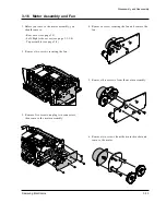
Page 23: ...ee page 3 3 Left Right side covers see page 3 3 3 4 Top assembly see page 3 8 2 Remove two screws securing the fan 3 Remove five screws unplug two connectors then remove the motor assembly 4 Remove a screw securing the fan and remove the fan 5 Remove three screws from the motor assembly 6 Remove two screws from the motor bracket and remove the motor ...

Page 24: ...lectronics Disassembly and Reassembly 3 17 Fuser 1 Before you remove the fuser you should remove Rear cover see page 3 3 2 Remove the exit actuator and unplug two connectors 3 Remove four screws then remove the fuser ...

Page 25: ...sembly Thermostat on the Fuser Remove two screws securing the thermostat and take it out Thermistor on the Fuser 1 Remove four screws and remove the upper cover 2 Remove the heat roller 3 Remove two screws securing the thermistor then take it out ...

Page 26: ... 1 Release the connector cable from its recessed channel Roller on the Fuser 1 Remove four screws and remove the upper cover 2 Remove the roller 2 Remove one screw and remove the halogen lamp Note When you reassemble the lamp make sure that the halogen lamp is inserted in place ...

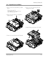
Page 27: ...ould remove Rear cover see page 3 3 Left Right side covers see page 3 3 3 4 Top assembly see page 3 8 2 Remove four screws and remove the right and left base brackets 3 Remove two screws and remove the ICU ground 4 Remove seven screws and release the latch securing the PCU shield 5 Unplug all connectors and remove PCU shield ...

Page 28: ...V terminals When you reassemble the terminals make sure that the terminals are inserted in place Transfer Guide Remove five screws and remove the transfer guide SCF Connector Remove two screws and remove the connector Cover Open Sensor Remove the spring and remove the sensor ...

Page 29: ...s Disassembly and Reassembly Pick up Sensor Squeeze both ends of the sensor and lift it up Transfer Roller Bushing Push them downward to be released Erase Lamp Remove two screws unplug one connector then remove the erase lamp ...

Page 30: ...s 3 20 Disassembly and Reassembly 3 Remove the pick up rubber Pull it up to remove the rubber 1 Remove two screws and remove the right base bracket 3 19 Pick up Assembly 2 Remove three screws and remove Pick up assembly ...

Page 31: ...Year 1 Year 10 000 Pages 20 000 Pages 50 000 Pages 50 000 Pages 6 000 Pages 50 000 Pages 50 000 Pages 50 000 Pages 30 000 Pages 4 2 Diagnostics This section describes methods and procedures to isolate the cause of a malfunction in the machine This machine displays diagnostic information on the LCD In addition it can perform a series of tests that allow the machine to observe individual machine fun...

Page 32: ...o document loaded LOAD DOCUMENT Load a document and try again The memory has become full MEMORY FULL Either delete unnecessary documents or retransmit after more memory becomes available or split the transmission into more than one operation The remote machine was not answered after all the redial attempts NO ANSWER Try again Make sure the remote machine is OK The one touch or speed dial location ...

Page 33: ...poll code The remote fax machine you want to poll is not ready to respond to your poll POLLING ERROR The remote operator should know in advance that you are polling and have their fax unit loaded with the original document A power failure has occurred POWER FAILURE If there has been documents stored in memory Power failure report will be printed automatically when the power is restored The machine...

Page 34: ...l of the Contact Image Sensor Check for the waveform in the pattern It is best when the wave form is level If there are many points sharply broken perform the Make shading procedure several times until you get a level waveform SWITCH TEST This test checks the operation of the LCD display and the LED indicators that interface the switches on the operation panel MODEM TEST This test causes the machi...

Page 35: ...sor On Off 3 MHV On Off Devbias On Off 4 SCF Motor On Off SCF Solenoid On Off SCF Paper Empty On Off SCF Installed 5 THV EN On Off THV On Off THV NEG On Off To enter the Engine test mode 1 Press Menu 1 9 3 1 in sequence 2 When you see ENGINE TEST press Start ENGINE TEST NO O 5 appears in LCD window 3 Enter the number you want 4 Scroll to the options by pressing or repeatedly until you find the one...

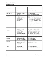
Page 36: ...5 Measure all high voltage output 6 Leakage toner cause bad contact and increase contact resistance Clean contaminated area 1 Check the rated level and replace 2 Set to power rating 3 Replace defected board 1 Adjust to the rated status 2 Replace Toner cartridge 1 Check every high voltage 2 Clean the inside machine or replace toner cartridge 1 Bad blade of Toner cartridge 2 LSU 1 LSU window contami...

Page 37: ...oner cartridge 3 Replace transfer roller 1 2 Change toner cartridge 3 Check left and right spring of transfer roller and the spring pressing the developer inside the machine 1 Clean each contact and check good contact 2 Clean charge roller 3 Replace fuser unit 4 Check engine B d 1 Contamination of transfer roller 2 Stains of paper path 3 Pressure roller s contamination 1 Use recommended paper 2 Ch...

Page 38: ...PC Drum 94 2mm White spot 2 Charge Roller 37 7mm Black spot 3 Supply Roller 31mm Horizontal density band 4 Develope Roller 46 7mm Horizontal density band 5 Transfer Roller 47 1mm Black side contamination transfer fault 6 Heat Roller 56 4mm Black spot White spot 7 Pressure Roller 56 5mm Black side contamination ...

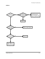
Page 39: ...troller engine board Repair or replace the defective component or board The mirror in LSU might be misplaced so the light path to the OPC deviates Repait or replace LSU or remove any deffective matters in the machine No image Is the OPC terminal of machine is well connected to Frame Does the video data line to LSU transit to High Low when printing A on nextpage NO NO NO YES YES YES No Image ...

Page 40: ...he transfer roller shaft Are the connection terminal and connection correct Repair or replace terminal Sealing tape is removed from the cartridge Replace Engine B d or repair defective component Is the connection terminal OK Replace Engine B d or repair defective component Repair or replace terminal Remove the tape Developing 300V and supplying 500V voltage are OK Does the counter indicate over th...

Page 41: ...received in LSU Transfer part s contact is bad Repair or replace toner cartridge Does the video data line to LSU transit to High Low when printing Replace LSU Check the path among video controller engine board LSU for the shortage or open Repair or replace the boards Repair or replace Engine B d Replace LSU NO NO NO NO YES YES YES YES All Black ...

Page 42: ... the transfer roller Toner material might be stuck to blade in the developer inside and it prevents toner supply Replace the developer Check both if the toner cartridge s counter is over its guaranty and amount of the toner material Replace the toner cartridge The ribs in fuser or toner on the roller may invoke the image problem Replace the fuser cover or the defective part The image is originally...

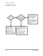
Page 43: ...of Bias voltage Works correctly after replaced LSU Repair or replace the defective component The power of LSU is set high or internal problem Replace LSU or adjust voluem Same at Normal END NO NO NO Toner over supply due to the adjustment fault of metering blade in developer Replace developer NO YES YES YES YES Dark Image ...

Page 44: ...charge roller or replace step up device terminal after check Work OK Internal blade or suppying part of the developer is defective Replace the toner cartridge Check Terminals or contacts and Guide Deve Spring are misplaced Repair or replace transfer roller etc Print 20 to 30 pages using the recommended paper Same problem occurs Adjust voltage or replace Engine B d Repair or replace after checking ...

Page 45: ...eEngine B d Check and Repair or replace the terminal contacts A specific part of the transfer roller has ruined or its resistance value is changed Replace transfer roller Transfer roller cannot force regularly due to the gears eccentricity of transfer roller Replace the defective component Bias voltage is OK 300V Operating storage temperature is too low or not recommended paper used Adjust the Bia...

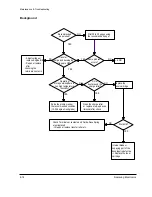
Page 46: ... Replace developer and C R When taking out the cartridge toner leaks Toner leaks and toner material dropped onto the paper Replace the developer Bad image removes by scratching Check toner is stuck onto the P R or H R in fuser Clean it or replace The problem randomly occured due to the toner fallen Clean the machine NO NO NO YES YES YES Black Dot ...

Page 47: ...replace the developer This occurs when no Hsync at LSU Replace LSU 94mm interval Heat roller is ruined Replace the roller The OPC is damaged due to the irregular transfer voltage of HVPS Repair replace Engine B d If the same problem persists replace the developer Does it appear at every 56 1mm at specific place Problems of terminal contact transfer voltage supplying and transfer roller s due to th...

Page 48: ...ing voltage drops while printing Defective agitator in the toner supplying part of developer Replace the developer Check if the guide deve spring works OK and repair repalce Check high voltage output and repair replace terminals Engine B d Bad images aroung the no image area Irregualrity of toner suppy from developer Repalce developer Light distortion due to the mirror ruined or LSU s diffused ref...

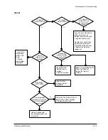
Page 49: ...n the OPC and machine or replace developer When putting in out the developer scratch is made Replace the developer Transfer voltage is normal D R in developing unit has the defect Replace the developer Too high voltage supplied due to the setting error of transfer voltage Adjust replace Engine B d NO NO YES YES White Spot ...

Page 50: ...for a long time Place the machine at normal temperature and re test While printing the voltage of pin 5 of U5 on engine board is about 2 7V Thermistor s contact is OK Open the top cover When black printing is the fuser NIP width is 3 0 3 5mm The paper used is too thick or contains too much cotton in it Re test with the recommended paper Check if the hardness of P R and spring force is OK hardness ...

Page 51: ...ended for Manual Feeding When loading tap the papers until paper detect sensor senses loading 5 When using long papers use the Stacker Extender 6 Adjust Guide to fit the paper width 1 It is mostly resulted from double feeding Check paper is well stocked in feeder 2 Check feed actuator position and actuator s operating There may be stiff movind or double reflection If not so check the operation of ...

Page 52: ...nd measure the voltage with high voltage probe and sending printing data If the voltage is normal change the toner cartridge 2 Check HV of in Engine B d and change it 1 Re insert the film neatly into the front When inserting it the Plate knockup needs to be aligned to the front 2 Turn the power off and on Open and close the Top cover to return to the original state Fit the paper width using the Gu...

Page 53: ...stacking capacity can be lowered depending on the type of papers Refer to troubleshooting ENGINE ERROR 1 Took out the Stacker extender to support long papers 2 Stacked too many papers more than Stacker can hold 3 Face up stacker does not neatly stack the papers and stack not in order 1 Check CBF Harness 5P 6P HVPS B D to LSU 2 Check CBF Harness 24P ENGINE B D to HVPS B D 3 Check CBF Harness 20P EN...

Page 54: ...g Connections on board are OK Re connect firmly and re test The connection error between controller board and panel board or malfunction of boards Replace the boards Fuse of SMPS if open Shortage between 5V and GND or between 24V and GND Replace the fuse Toner cartridge is in the set Detect failure due to the board which detects top cover open or switch error Replace the board or switch Put in the...

Page 55: ... due to the heat etc Replace the thermostat Check the voltage of pin 6 of U5 if it is about 2 3 it s OK if not check the CON4 in Power B d Measure the resistance at the both ends of AC Line with covers open Remove the Rear covers Re assemble the top cover and close it Thermistor connecting point or engine board defect Repair replace the component board NO NO NO YES YES YES Fuser Error ...

Page 56: ...or and paper width detect sensor are assembled reverse Switch them The sensor and joint boards defected Repair replace Too many papers in the feeder Paper guides fit the paper width Paper end curled Does the extender pulled out Recommendation Use the MPF for the thick paper such as envelope and cardstock Reduce the amount and re test Take out the paper and re insert Use the recommended and quality...

Page 57: ...y Use the recommended paper Check guide transfer is grounded Check the shutter prevents feeding Check the input path to the fuser such as mis assembly The actuator of paper exit sensor works OK Check the actuator exists and its operation and around the engine board Replace Is the paper rolled around the presseure roller Remove the fuser remove the paper and replace the pressure roller if necessary...

Page 58: ...4 28 Samsung Electronics Maintenance Troubleshooting MEMO ...

Page 59: ...75B Msys6750 JC96 01475C SF 6800I XEF SF 6800I XEG SF 6800I XEU SEC CODE BYUER JC92 01136A Msys6800 JC92 01136B Msys6750 JC92 01136C SF 6800I XEF SF 6800I XEG SF 6800I XEU SEC CODE BYUER JC74 00004A Msys6800 SF 6800I XEU JC74 00004B Msys6750 JC74 00004D SF 6800I XEF JC74 00004E SF 6800I XEG SEC CODE BYUER JC72 00095A Msys6800 Msys6750 JC72 00095E SF 6800I XEF JC72 00095F SF 6800I XEG JC72 00095D S...

Page 60: ...ly Parts Lists 5 5 Fuser Assembly Fuser Assembly Parts Lists 5 6 TX Unit Assembly TX Unit Assembly Parts Lists 5 7 Pick Up Assembly Pick Up Assembly Parts Lists 5 8 Motor Assembly Motor Assembly Parts Lists 5 9 PCU Assembly PCU Assembly Parts Lists 5 10 Cassette Assembly Cassette Assembly Parts Lists 5 11 Second Cassette Frame Assembly Second Cassette Frame Assembly Parts Lists Samsung Electronics...

Page 61: ...loded Views and Parts Lists 5 2 Samsung Electronics 5 1 Main Assembly 9 12 2 12 3 12 4 10 22 23 22 1 22 2 8 7 6 2 1 5 4 3 18 17 16 16 1 12 12 1 S3 S1 S5 13 14 15 21 20 19 24 16 2 11 S2 11 4 11 1 11 2 11 3 ...

Page 62: ... 1 PMO COVER SIDE R 1 N 12 2 SPEAKER 3001 001044 1 Y 12 3 IPR UNIT FIXING BRAC GB70 10500A 1 Y 12 4 CBF HARNESS SPK MAIN JC39 00028A 1 Y 13 CBF HARNESS JC39 40006A 1 Y 14 PMO ACTUATOR EXIT JC72 40339A 1 Y 15 ELA HOU FUSER JC96 01468A 1 Y 110V ELA HOU FUSER JC96 01468B 1 Y 220V 16 ELA HOU MAIN B D ASS Y refertheinformation 1 Y 16 1 IPR BRKT MAIN JC70 00025A 1 Y 16 2 PBA MAIN MAIN refertheinformatio...

Page 63: ...Exploded Views and Parts Lists 5 4 Samsung Electronics 5 2 Top Assembly 10 9 0 9 2 9 1 9 3 8 9 4 11 13 12 20 7 5 16 17 6 4 3 1 2 15 15 1 15 2 15 3 14 19 18 ...

Page 64: ...10538A 1 Y 9 1 RING C 6044 000159 2 Y 9 2 PMO BUSHING WHITE JF72 41306A 2 Y 9 3 MEC ROLLER CIS 1 N 9 4 PMO GEAR DRIVE B4 JG72 40740A 1 Y 10 ELA HOU OPE ASS Y 1 N 11 PMO DOC GUIDE L JC72 41301E 1 Y 12 GEAR PINION JG66 40003A 1 Y 13 PMO DOC GUIDE R JC72 41300E 1 Y 14 ELA HOU SCAN LOWER 1 N 15 MEA UNIT BUTTON C O 1 N 15 1 PMO BUTTON C O HOUSING 1 Y 15 2 PMO BUTTON C O 1 Y 15 3 SPRING OPEN P JC61 7097...

Page 65: ...Exploded Views and Parts Lists 5 6 Samsung Electronics 5 3 OPE Unit Assembly 10 11 12 13 0 6 5 7 8 14 15 4 9 3 16 S1 S4 17 2 1 1 5 1 3 1 15 1 11 1 1 1 12 1 2 1 10 1 4 1 7 1 13 1 14 1 9 1 8 1 6 S2 S3 ...

Page 66: ...40A 1 Y 1 11 PMO SUPPORT ADF JG72 41083A 1 Y 1 12 PMO LEVER SENSOR JC72 41322A 1 Y 1 13 CBF HARNESS PINCH GND JC39 00026A 1 Y 1 14 RPR SPONGE SDF 1 N 1 15 MPR TAPE ADF 1 N 2 PBA SUB OPE JC81 00279A 1 Y 3 RMO RUBBER SCROLL 1 N 4 RMO RUBBER ONETOUCH 1 N 5 PMO KEY START 1 N 6 PMO KEY COPY 1 N 7 PMO KEY STOP 1 N 8 PMO KEY SCROLL 1 N 9 PMO KEY ONETOUCH 1 N 10 MPR COVER ADDRESS 1 N 11 MPR PAPER ADDRESS ...

Page 67: ...sts 5 8 Samsung Electronics 5 4 Frame Assembly 18 18 1 18 2 18 3 18 4 21 21 1 21 2 21 3 22 20 19 17 0 23 24 16 16 1 16 1 16 2 29 30 1 31 30 25 27 26 S1 28 15 13 S1 14 12 10 9 7 5 8 6 32 32 1 32 2 3 2 2 2 1 2 3 2 S2 1 S1 2 4 4 11 ...

Page 68: ... Y 16 2 PMO GUIDE DEV L JC72 40274A 1 Y 17 GROUND TRANSFER PLATE JC70 10215B 1 Y 18 MEA ETC TRANSFER HOL JC97 00901A 1 Y 18 1 PMO BUSH JC72 40228A 1 Y 18 2 SPRING CS 6107 000115 1 Y 18 3 BEARING HOLDER TR JC66 10204A 1 Y 18 4 SPRING PLATE TR JC61 70203A 1 Y 19 PMO SPACER TR JC72 40686A 1 Y 20 MEC ROLLER TRANSFER JC75 10916A 1 Y 21 MEC TRANSFER HOL R JC75 00067A 1 Y 21 1 PMO BUSHING TR12 R JC72 410...

Page 69: ...5 5 Fuser Assembly 21 S2 S2 S3 25 S1 S2 24 26 27 0 28 19 17 18 20 16 32 33 22 23 15 14 29 31 30 12 13 7 9 8 5 3 2 9 10 11 4 1 6 Exploded Views and Parts Lists 5 10 Samsung Electronics ...

Page 70: ...NG ES 4 N 16 PMO FRAME UPPER FUSER 1 N 17 GEAR EXIT U ID 1 N 18 GEAR EXIT L ID 1 N 19 RING CS 3 N 20 NPR ELECTRODE FU L 1 N 21 CBF HARNESS JC39 40019A 1 Y 110V CBF HARNESS JC39 40007A 1 Y 220V 22 THERMOSTAT 1 N 23 LABEL R HOT FU 1 N 24 NPR ELECTRODE FU R 1 N 25 SPRING THERMIST 1 N 26 PMO ROLLER EXIT F UP JC72 40342A 2 Y 27 SPRING PS EXIT F UP 2 N 28 THERMISTOR NTC 1404 000001 1 Y 29 LAMP HALOGEN 4...

Page 71: ...Exploded Views and Parts Lists 5 12 Samsung Electronics 4 6 7 7 1 7 2 7 3 7 4 7 5 7 6 6 1 6 2 6 3 4 4 5 8 S1 S1 S1 0 3 2 1 15 14 S2 10 13 9 11 12 S1 S3 19 18 17 16 S3 5 6 TX Unit Assembly ...

Page 72: ... RING C 6044 000156 1 Y 7 2 MEC ROLLER ADF JG75 10016A 1 Y 7 3 ICT SHAFT ADF JG70 40547A 1 Y 7 4 PMO BUSHING HOLDER JG72 40732A 1 Y 7 5 ICT SPRING CLUTCH JG70 40534A 1 Y 7 6 PMO GEAR ADF JG72 40659A 1 Y 8 IPR GROUND DRIVE JG70 10006A 1 Y 9 PMO SCAN LOWER 1 N 10 GEAR SPUR JG66 40001A 3 Y 11 GEAR IDLE4920 JG66 40040A 1 Y 12 CBF HARNESS EARTH CIS 1 N 13 GEAR IDLE3315 JG66 40041A 1 Y 14 LOCKER TX JG64...

Page 73: ...Exploded Views and Parts Lists 5 14 Samsung Electronics 5 7 Pick Up Assembly 7 3 2 3 2 8 9 10 6 5 11 15 4 1 17 18 19 20 22 21 2 3 16 2 12 3 13 14 24 23 21 S1 0 ...

Page 74: ...RING PICK UP 12 JC61 70966A 1 Y 11 PMO FRAME FEED 1 N 12 PMO IDLE PICK UP JC72 41234A 1 Y 13 PMO HOUSING P UP JC72 40252A 1 Y 14 PMO RUBBER PICK UP JC73 40907A 1 Y 15 IPR GUIDE FEED JC70 10992A 1 Y 16 PMO ROLL FEED DRV 12 JC72 41295A 1 Y 17 SPRING FEED 2 JC61 70942A 1 Y 18 PMO HOLDER FEED 2 JC72 41185A 1 Y 19 PMO SUB HOLDER FEED JC72 40266A 1 Y 20 PMO ROLLER FEED S JC72 40262A 1 Y 21 IPR SHAFT FEE...

Page 75: ... 1 Y 1 IPR BRKT GEAR JC70 10903A 1 Y 2 FAN MOTOR FAN JC31 30502B 1 Y 3 GEAR FUSER DRIVE 1 N 4 GEAR IDLE FU 1 N 5 GEAR 125 18 1 N 6 IPR BRKT MOTOR 1 N 7 MOTOR STEP JC31 10100F 1 Y 8 CABLE TIE 6501 000115 2 Y 9 GEAR 132 25 1 N 10 GEAR IDLE OPC 1 N 11 GEAR OPC DRV2 1 N 12 GEAR OPC DRIVE 1 N 13 GEAR FEED DRV 1 N S1 SCREW MACHINE 6 N Motor Assembly Parts Lists SA Service Available Not Serviceable ...

Page 76: ...ription SEC Code Q ty SA Remark 0 MEC SHIELD ASS Y JC75 00065A 1 Y 1 NPR SHIELD PCU JC71 10320A 1 Y 2 RCT FOOT PCU JC73 30911A 2 Y 3 PPR INSULATOR PCU JC72 10379A 1 Y 4 SUPPORTER 1 N 5 SUPPORTER 6103 001040 2 Y 6 PPR INSULATOR IC JC72 10901A 1 Y PCU Assembly Parts Lists SA Service Available Not Serviceable ...

Page 77: ...5 18 Samsung Electronics Exploded Views and Parts Lists 5 10 Cassette Assembly 3 4 5 6 8 9 11 12 7 13 10 2 1 S1 S1 23 21 20 18 0 17 14 15 16 19 24 22 ...

Page 78: ...Y 9 PMO LOCKER PLATE JC72 41210A 1 Y 10 IPR PLT KNOCK UP 12 JC70 11022A 1 Y 11 RPR MMP PAD 1 N 12 LABEL R PLATE 1 N 13 SPRING LOCKER PLATE JG61 70531A 1 Y 14 PMO GUIDE REAR JC72 41180A 1 Y 15 PMO GUIDE LETTER JC72 41392A 1 Y 16 IPR TENSION LETTER JC70 11085A 2 Y 17 IPR BRACKET LETTER JC70 11087A 1 Y 18 IPR BRACKET LEGAL JC70 11086A 1 Y 19 PMO GUIDE LEGAL JC72 41393A 1 Y 20 PMO ADJUSTER S CAST JC72...

Page 79: ... 5 11 Second Cassette Frame Assembly 37 S1 39 S1 36 S1 35 25 S5 26 27 28 34 32 29 30 3 3 31 40 S1 S1 22 3 S7 42 43 S2 3 4 S1 S2 6 5 S1 1 2 3 4 7 23 8 12 13 7 S1 24 19 S3 18 20 21 S1 3 22 11 S4 S3 16 17 S1 7 15 14 S1 10 9 S1 S6 6 41 S1 33 23 38 44 0 Top side ...

Page 80: ...N 20 COLLAR CLUTCH P1 1 N 21 GEAR P UP OPTION 1 N 22 BEARING FEED 2 N 23 GUIDE RAIL 2 N 24 PBA MAIN 1 N 25 FRAME LEFT SCF 1 N 26 ACTUATOR ARM 1 N 27 CS STOP RING 1 N 28 PIN PARELLED P U N 29 HODER HOUSING 1 N 30 RUBBER P UP 1 N 31 IDLE SCF 1 N 32 SHAFT PICKUP 1 N 33 FRAME LOWER 1 N 34 STOPPER SCF 1 N 35 CBF HARNESS 1 N 36 LABEL WARNING 1 N 37 LABEL R SCF 12 1 N 38 COVER REAR 1 N 39 FRAME UPPER 1 N...

Page 81: ...5 22 Samsung Electronics Exploded Views and Parts Lists MEMO ...

Page 82: ...000028 R86 R87 2 R CHIP 39OHM 5 1 10W DA TP 2012 2007 000029 R111 R127 R128 3 R CHIP 0OHM 5 1 10W DA TP 2012 2007 000029 R131 R142 2 R CHIP 0OHM 5 1 10W DA TP 2012 2007 000029 R23 R64 R96 R97 4 R CHIP 0OHM 5 1 10W DA TP 2012 2007 000221 R52 1 R CHIP 1 2KOHM 5 1 10W DA TP 2012 2007 000241 R37 R146 2 R CHIP 1 5KOHM 5 1 10W DA TP 2012 2007 000282 R22 R27 R30 3 R CHIP 100KOHM 5 1 10W DA TP 2012 2007 0...

Page 83: ...00192 C18 C19 C20 C22 4 C CERAMIC CHIP 100nF 80 20 50V Y5V TP 2012 2203 000192 C23 C24 C26 C27 4 C CERAMIC CHIP 100nF 80 20 50V Y5V TP 2012 2203 000192 C29 C31 C34 C35 4 C CERAMIC CHIP 100nF 80 20 50V Y5V TP 2012 2203 000192 C38 C40 C43 C47 4 C CERAMIC CHIP 100nF 80 20 50V Y5V TP 2012 2203 000192 C49 C56 C57 3 C CERAMIC CHIP 100nF 80 20 50V Y5V TP 2012 2203 000192 C64 C65 C66 C69 4 C CERAMIC CHIP ...

Page 84: ...K 5V 20mA 2901 000229 F1 F2 2 FILTER EMI SMD 50V 300mA 22nF 4 5x1 8x3 2mm 3702 001001 CN6 1 CONNECTOR RIBBON 36P FEMALE ANGLE AUF 3711 000398 CN2 1 CONNECTOR HEADER BOX 10P 1R 2mm STRAIGHT SN 3711 000443 CN1 1 CONNECTOR HEADER BOX 2P 1R 2mm STRAIGHT SN 3711 000470 CN3 CN9 2 CONNECTOR HEADER 3WALL 4P 1R 2mm STRAIGHT SN 3711 000484 CN8 CN12 2 CONNECTOR HEADER 3WALL 5P 1R 2mm STRAIGHT SN 3711 000665 ...

Page 85: ...HM 5 1 10W DA TP 2012 2007 000029 R111 R127 R128 3 R CHIP 0OHM 5 1 10W DA TP 2012 2007 000029 R131 R142 R60 R61 4 R CHIP 0OHM 5 1 10W DA TP 2012 2007 000029 R23 R64 R96 R97 4 R CHIP 0OHM 5 1 10W DA TP 2012 2007 000221 R52 1 R CHIP 1 2KOHM 5 1 10W DA TP 2012 2007 000241 R37 R146 2 R CHIP 1 5KOHM 5 1 10W DA TP 2012 2007 000282 R22 R27 R30 3 R CHIP 100KOHM 5 1 10W DA TP 2012 2007 000290 R126 R138 R13...

Page 86: ...2012 2203 000192 C49 C56 C57 3 C CERAMIC CHIP 100nF 80 20 50V Y5V TP 2012 2203 000192 C64 C65 C66 C69 4 C CERAMIC CHIP 100nF 80 20 50V Y5V TP 2012 2203 000192 C73 C74 C77 C84 4 C CERAMIC CHIP 100nF 80 20 50V Y5V TP 2012 2203 000192 C85 C91 C92 C94 4 C CERAMIC CHIP 100nF 80 20 50V Y5V TP 2012 2203 000192 C95 C96 C98 3 C CERAMIC CHIP 100nF 80 20 50V Y5V TP 2012 2203 000239 C115 C116 C117 3 C CERAMIC...

Page 87: ...OR RIBBON 36P FEMALE ANGLE AUF 3711 000398 CN2 1 CONNECTOR HEADER BOX 10P 1R 2mm STRAIGHT SN 3711 000443 CN1 1 CONNECTOR HEADER BOX 2P 1R 2mm STRAIGHT SN 3711 000470 CN3 CN9 2 CONNECTOR HEADER 3WALL 4P 1R 2mm STRAIGHT SN 3711 000484 CN8 CN12 2 CONNECTOR HEADER 3WALL 5P 1R 2mm STRAIGHT SN 3711 000665 CN7 1 CONNECTOR HEADER BOX 12P 1R 2mm ANGLE SN 3711 000865 CN11 1 CONNECTOR HEADER BOX 3P 1R 2mm ST...

Page 88: ... 5 1 2W AA TP 2 4X6 4MM 2001 000221 R39 1 R CARBON 1 2KOHM 5 1 8W AA TP 1 8X3 2MM 2001 000273 R215 R238 R281 R282 4 R CARBON 100KOHM 5 1 8W AA TP 1 8X3 2MM 2001 000281 R15 R24 R29 R71 R81 5 R CARBON 100OHM 5 1 8W AA TP 1 8X3 2MM 2001 000281 R73 R290 R291 R292 4 R CARBON 100OHM 5 1 8W AA TP 1 8X3 2MM 2001 000290 R278 1 R CARBON 10KOHM 5 1 8W AA TP 1 8X3 2MM 2001 000362 R16 R23 2 R CARBON 150OHM 5 1...

Page 89: ...0 20 500V Y5V TP 13 5x 2201 000119 C226 C227 C229 3 C CERAMIC DISC 100nF 80 20 50V Y5V TP 8x3 5 2201 000119 C26 C46 C37 C77 4 C CERAMIC DISC 100nF 80 20 50V Y5V TP 8x3 5 2201 000119 C78 C79 C209 C222 4 C CERAMIC DISC 100nF 80 20 50V Y5V TP 8x3 5 2201 000138 C30 C31 2 C CERAMIC DISC 100pF 10 50V Y5P TP 4 0X4 0 2 2201 000162 C300 C301 2 C CERAMIC DISC 10NF 80 20 50V Y5V TP 6 3X3 5 2201 000177 C217 C...

Page 90: ...C39 40511A JP25 JP27 JP28 JP31 4 CBF HARNESS ML 80 JUMPER AWG22 52mm SILVER JC39 40511A JP305 JP306 2 CBF HARNESS ML 80 JUMPER AWG22 52mm SILVER JC39 40511A JP307 JP309 JP310 JP311 4 CBF HARNESS ML 80 JUMPER AWG22 52mm SILVER JC39 40511A JP312 JP314 JP315 JP317 4 CBF HARNESS ML 80 JUMPER AWG22 52mm SILVER JC39 40511A JP318 JP320 2 CBF HARNESS ML 80 JUMPER AWG22 52mm SILVER JC39 40511A JP32 JP33 JP...

Page 91: ...0822 R27 1 R CHIP 390OHM 5 1 10W DA TP 2012 2203 000206 C5 C6 C7 C8 C9 5 C CERAMIC CHIP 100nF 10 50V X7R TP 2012 2203 000239 C10 C11 C12 3 C CERAMIC CHIP 0 1nF 5 50V NP0 TP 2012 2203 000595 C2 C3 C4 3 C CERAMIC CHIP 0 22nF 5 50V NP0 TP 2012 2203 001002 C13 C14 2 C CERAMIC CHIP 0 047nF 5 50V NP0 TP 2012 2401 000414 C15 1 C AL 10uF 20 16V GP TP 4x7 5 2802 000185 X1 1 RESONATOR CERAMIC 7 37MHz 0 5 TP...

Page 92: ...IP 30KOHM 5 1 10W DA TP 2012 2007 000872 R18 1 R CHIP 4 7KOHM 5 1 10W DA TP 2012 2007 000931 R14 1 R CHIP 470OHM 5 1 10W DA TP 2012 2007 001092 R23 1 R CHIP 620OHM 5 1 10W DA TP 2012 2007 001118 R3 1 R CHIP 680OHM 5 1 10W DA TP 2012 2203 000239 C18 C19 2 C CERAMIC CHIP 0 1nF 5 50V NP0 TP 2012 2203 000455 C14 1 C CERAMIC CHIP 1nF 5 50V NP0 TP 2012 2203 000609 C10 1 C CERAMIC CHIP 22nF 10 50V X7R TP...

Page 93: ... 2 R CARBON 82KOHM 5 1 8W AA TP 1 8X3 2MM 2201 000017 C1 C2 2 C CERAMIC DISC 1nF 10 50V Y5P TP 4x3 5 5 2201 000138 C12 C13 2 C CERAMIC DISC 100pF 10 50V Y5P TP 4 0X4 0 2 2201 000558 C14 C15 2 C CERAMIC DISC 470pF 10 50V Y5P TP 5x3 5 2202 000632 C4 C9 C11 7 C CERAMIC MLC AXIAL 100nF 20 50V Z5U TP 2 5x4 3 2401 000480 C3 C10 2 C AL 10uF 20 50V GP TP 5x11 5 2802 000154 X1 1 RESONATOR CERAMIC 480KHz 0 ...

Page 94: ... I 4 0 4 h f 7 h g H e W 2 6 K f 3 h e 7 g 7 g L H h f I 4 7 H e 7 O 2 h e X e 7 H h e Y f f 7 h V 6 K e O 2 7 I 4 K e 7 J h V Y 3 h g f f N 1 h e g 5 g 1 h f I 4 3 e 3 O 2 h e 3 X e 3 N f f N M I 3 h e V 4 0 M 1 I 4 6 X 3 h h f 6 X N h g 3 g I M g 3 h e g H g 5 L h f 3 I N L e N h e O 2 0 M I h e V 4 e N h X f g Y V N h f I 4 0 M 3 I 4 N N h h f K h g g N H h h e 3 L f J h H 1 h f N e h O 2 M f V...

Page 95: ...MEMO Samsung Electronics 8 2 ...

Page 96: ...PCB Diagrams Samsung Electronics 9 1 9 1 Main PCB Diagram Top 9 PCB Diagrams ...

Page 97: ...PCB Diagrams Samsung Electronics 9 2 9 2 Main PCB Diagram Bottom ...

Page 98: ...PCB Diagrams Samsung Electronics 9 3 9 3 LIU PCB Diagram Top 9 4 LIU PCB Diagram Bottom ...

Page 99: ...PCB Diagrams Samsung Electronics 9 4 9 5 Engine PCB Diagram Top ...

Page 100: ...PCB Diagrams Samsung Electronics 9 5 Engine PCB Diagram Top ...

Page 101: ...PCB Diagrams Samsung Electronics 9 6 9 6 Engine PCB Diagram Bottom ...

Page 102: ...PCB Diagrams Samsung Electronics 9 7 Engine PCB Diagram Bottom ...

Page 103: ...PCB Diagrams Samsung Electronics 9 8 9 7 OPE PCB Diagram ...

Page 104: ...PCB Diagrams Samsung Electronics 9 9 OPE PCB Diagram ...

Page 105: ...PCB Diagrams Samsung Electronics 9 10 MEMO ...

Page 106: ...Connection diagram Samsung Electronics 8 1 8 Connection diagram ...

Page 107: ...MEMO Samsung Electronics 8 2 ...

Page 108: ...75 176 GIOP7 GIOP8 177 GIOP9 178 GND1 11 172 GND10 181 GND11 GND2 25 GND3 206 GIOP0 137 GIOP1 138 GIOP10 179 GIOP2 139 GIOP3 140 GIOP4 173 GIOP5 174 GIOP6 65 D7 66 68 D8 D9 69 116 DC_SIN0 GPI DC_SIN1 GPI 117 208 GAD_IN0 GAD_IN1 207 GAD_IN2 72 D13 73 D14 74 D15 75 61 D2 D3 62 D4 63 D5 64 D6 112 CRIB1 GPO 114 110 CR_PHA GPO CR_PHB GPO 113 59 D0 D1 60 D10 70 D11 71 D12 A8 A9 87 BUSY 158 CIS_CLK 6 CIS...

Page 109: ...00nF C104 D7 RB420D T147 C103 100nF VB KIA7045P U19 2 3 1 100 R141 100 R140 100 R139 100nF C99 R148 820 VSB R145 R147 220K 180K C123 10nF VB 8 13 12 11 3 10 9 U20 1 CD74HC08M 7 GND 1 2 VCC 14 VSB VSB KSA1182 Y Q7 1 3 2 nRESET D 0 15 A 0 21 nSRAMCS nWTD_OUT A 10 A 21 A 10 A 21 nRD nWR D 13 D 14 D 15 D 1 D 2 D 3 D 4 D 5 D 6 D 7 D 8 A 18 nWR nD_CAS1 nD_RAS0 nD_CAS0 D 0 D 9 D 10 D 11 D 12 D 13 D 14 D ...

Page 110: ...Main Circuit Diagram 3 5 Samsung Electronics 10 3 Schematic Diagrams ...

Page 111: ...Schematic Diagrams 10 4 Samsung Electronics Main Circuit Diagram 4 5 ...

Page 112: ...Main Circuit Diagram 5 5 Samsung Electronics 10 5 Schematic Diagrams 220 C118 100pF C119 100pF C120 100pF C117 100pF C116 100pF C115 100pF ...

Page 113: ...Schematic Diagrams 10 6 Samsung Electronics 10 2 Engine Circuit Diagram 1 4 ...

Page 114: ...Engine Circuit Diagram 2 4 Samsung Electronics 10 7 Schematic Diagrams ...

Page 115: ...Schematic Diagrams 10 8 Samsung Electronics Engine Circuit Diagram 3 4 ...

Page 116: ...Engine Circuit Diagram 4 4 Samsung Electronics 10 9 Schematic Diagrams ...

Page 117: ...Schematic Diagrams 10 10 Samsung Electronics 10 3 LIU Circuit Diagram ...

Page 118: ...10 4 OPE Circuit Diagram Samsung Electronics 10 11 Schematic Diagrams D6 D5 D4 D3 D2 D1 D0 D6 D5 D0 D1 D2 D3 D4 ...

Reviews: