background image

Samsung Electronics

6. Troubleshooting

6-1

PRECAUTION!

1. CHECK GROUNDING BEFORE CHECKING FOR TROUBLE.
2. BE CAREFUL OF THE HIGH VOLTAGE CIRCUIT.
3. DISCHARGE THE HIGH VOLTAGE CAPACITOR.
4. WHEN CHECKING THE CONTINUITY OF THE SWITCHES OR TRANSFORMER, DISCONNECT ONE LEAD WIRE FROM THESE

PARTS AND THEN CHECK CONTINUITY WITHOUT THE POWER SOURCE ON. TO DO OTHERWISE MAY RESULT IN A FALSE
READING OR DAMAGE TO YOUR METER.

5. DO NOT TOUCH ANY PART OF THE CIRCUIT OR THE CONTROL CIRCUIT BOARD, SINCE STATIC DISCHARGE MAY DAMAGE IT.

ALWAYS TOUCH GROUND WHILE WORKING ON  IT TO DISCHARGE ANY STATIC CHARGE BUILT UP.

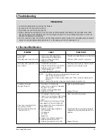
6-1 Electrical Mulifunction

SYMPTOM

CAUSE

CORRECTIONS

Oven is dead.

1. Open or loose lead wire harness

Check fan motor when thermal cutout is defective.

Fuse is OK.

2. Open thermal cutout (Magnetron)

No display and no operation at all. 3. Open low voltage transformer

Check Ass'y PCB when LVT is defective.

4. Defective Ass'y PCB

No display and no operation at all. 1. Shorted lead wire harness

Check adjustment of primary, interlock monitor,

Fuse is blown.

2. Defective primary latch switch (NOTE 1)

power relay, door sensing switch.

3. Defective monitor switch (NOTE1)
4. Shorted HVCapacitor
5. Shorted HVTransformer (NOTE2)

NOTE 1:   All of these switches must be replaced at the same time.

(refer to adjustment instructions)
Check continuity of power relay contacts and if it has continuity, replace power 
relay also.

NOTE 2:   When HVTransformer is replaced, check diode and magnetron also.

Oven does not accept 

1. Key input is not in-Sequence

Refer to operation procedure.

key input (Program)

2. Open or loose connection of membrane

key pad to Ass'y PCB

3. Shorted or open membrane panel
4. Defective Ass'y PCB

Replace PCB main.

1. Off-alignment of latch switches

Adjust door and latch switches.

2. Open or loose connection of high voltage

circuit especially magnetron filament
circuit

NOTE: Large contact resistance will bring 
lower magnetron filament voltage and 

Timer starts countdown but no

cause magnetron to lower output and/or

microwave oscillation.

intermittent oscillation.

(No heat while oven lamp and 

3. Defective high voltage components

Check high voltage component according to 

fan motor turn on.)

H.V.Transformer

component test procedure and replace if it is 

H.V.Capacitor

defective.

H.V.Diode
Magnetron

4. Open or loose wiring of power relay
5. Defective primary latch switch
6. Defective power relay or Ass'y PCB

Replace PCB main.

Summary of Contents for MS5796W

Page 1: ...VICEManual MICROWAVE OVEN CONTENTS 1 Precaution 2 Specifications 3 Operating Instructions 4 Disassembly and Reassembly 5 Alignment and Adjustments 6 Troubleshooting 7 Exploded Views and Parts List 8 PCB Diagrams 9 Schematic Diagrams SEA ...

Page 2: ... or inspection within the microwave generating compartments check the magnetron wave guide or transmission line and cavity for proper alignment integrity and connections d Any defective or misadjusted components in the interlock monitor door seal and microwave generation and transmission systems shall be repaired replaced or adjusted by procedures described in this manual before the oven is releas...

Page 3: ...nicians should remove their watches while repairing an MWO 11 To avoid any possible radiation hazard replace parts in accordance with the wiring diagram Also use only the exact replacements for the following parts Primary and secondary interlock switches interlock monitor switch 12 If the fuse is blown by the Interlock Monitor Switch Replace all of the following at the same time Primary door sensi...

Page 4: ...ive terminal of the high voltage capacitor to the oven chassis Use a screwdriver 3 High voltage is maintained within specified limits by close tolerance safety related components and adjustments If the high voltage exceeds the specified limits check each of the special components 1 2 Pretaution Samsung Electronics 1 2 Special Servicing Precautions Continued 1 3 Special High Voltage Precautions PRE...

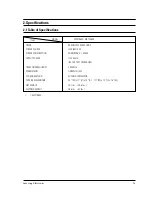
Page 5: ...CE 120V 60HZ AC POWER CONSUMPTION MICROWAVE 1 450W OUTPUT POWER 1100 Watts IEC 705 TEST PROCEDURE OPERATING FREQUENCY 2 450MHz MAGNETRON OM75PH 31 ESS COOLING METHOD COOLING FAN MOTOR OUTSIDE DIMENSIONS 2011 32 W x 1111 16 H x 1429 32 D 217 8 W x 125 16 H x 1621 32 D NET WEIGHT 35 3 lbs 38 6 lbs SHIPPING WEIGHT 38 6 lbs 43 lbs MS7796W ...

Page 6: ...evel Sets power to level other than high Clock Sets current time Start Press to start cooking Pause Canel Press to pause oven or correct a mistake Kitchen Timer Sound Button 1 2 3 6 4 5 8 7 0 9 Clock Kitchen Timer Auto Defrost Sensor Reheat Pause Cancel Start More Less Sensor Cook Fish Popcorn Potato Fresh Vegetable Frozen Dinner Frozen Breakfast Baby Food Diet Cook Help Screen One Minute Gentle C...

Page 7: ...e back panel of fan motor assembly 6 Take out the fan motor assembly 7 Remove the oven lamp by pulling out from hole of air cover NOTE1 When removing the magnetron make sure that its antenna does not hit any adjacent parts or it may be damaged NOTE2 When replacing the magnetron be sure to remount the magnetron gasket in the correct position and make sure the gasket is in good condition 1 Discharge...

Page 8: ... a thin metal plate between Door E and Door A until you hear the tick sound Insertion depth of the thin metal plate should be 0 5mm or less Insert flat screwdriver into the gap between Door A and Door C to remove Door C Be careful when handling Door C because it is fragile Then remove the door assembly 4 3 1 Removal of Door C 4 3 2 Removal of Door E Disassembly and Reassembly Door C Door A Door E ...

Page 9: ...defective component parts of the door reassemble it and follow the instructions below for proper installation and adjustment so as to prevent an excessive microwave leakage 1 When mounting the door to the oven be sure to adjust the door parallel to the bottom line of the oven face plate by moving the upper hinge and lower hinge in the direction necessary for proper alignment 2 Adjust so that the d...

Page 10: ... control box 4 When reconnecting the FPC connector make sure that the holes on the connector are properly engaged with the hooks on the Plastic Fastener 1 Window display should not be disassembled as its mounting tabs will be broken If repair work is difficult replace with Ass y control panel 2 The membrane key board is attached to the escutcheon base with doublefaced adhesive tape Therefore apply...

Page 11: ...should read open 1 The low voltage transformer is located on the control circuit board 2 Remove the low voltage transformer from the PCB Ass y and check continuity 3 Normal resistor reading is shown in the table PRECAUTION 1 High voltage is present at the high voltage terminals during any cook cycle 2 It is neither necessary nor advisable to attempt measurement of the high voltage 3 Before touchin...

Page 12: ...n assembly adjust the Latch Body by moving it so that the oven door will not have any play in it Check for play in the door by pulling the door assembly Make sure that the latch keys move smoothly after adjustment is completed Completely tighten the screws holding the Latch Body to the oven assembly 4 Reconnect to Monitor switch and check the continuity of the monitor circuit and all latch switche...

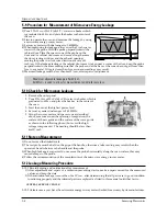
Page 13: ...ir the water again with the thermometer and measure the temperature T2 5 Subtract T1 from T2 This will give you the water temperature rise DT 6 The output power is obtained by the following formula 7 Normal temperature rise for this model is 9 9ûC to 10 5ûC at HIGH NOTE 1 Variations or errors in the test procedure will cause a variance in the temperature rise Additional power test should be made i...

Page 14: ...r of a radiarion preventing device make a repair record for the measured values and keep the data 2 If the radiation leakage is more than 5 mW cm2 after determining that all parts are in good condition functioning properly and the identical parts are replaced as listed in this manual notift that fact to CENTRAL SERVICE CENTER 5 12 2 At least once a year have the microwave energy survey meter check...

Page 15: ...r sensing switch 3 Defective monitor switch NOTE1 4 Shorted HVCapacitor 5 Shorted HVTransformer NOTE2 NOTE 1 All of these switches must be replaced at the same time refer to adjustment instructions Check continuity of power relay contacts and if it has continuity replace power relay also NOTE 2 When HVTransformer is replaced check diode and magnetron also Oven does not accept 1 Key input is not in...

Page 16: ... 1 Loose fan and fan motor Tighten screws of fan motor 2 Loose screws on H V Transformer Tighten screws of H V Transformer 3 Shorted H V Diode Replace H V Diode Turntable motor does not rotate 1 Open or loose wiring of turntable motor Check the wire of turntable motor 2 Defective turntable motor Replace turntable motor Oven stops operation during cooking 1 Open or loose wiring of primary Adjust do...

Page 17: ...odors during the cooking process The sensor is a plug in device located on the left side of the cavity at the cavity exhaust AUTO COOK TEST SENSOR ONLY 1 Place 1 3 cup tap water in oven 2 Touch POPCORN 3 After 1 2 mins Control Beeps Display counts down 4 Touch CLEAR OFF A Test OK Normal B Test Fails Check Sensor See Sensor Test SENSOR TEST QUICK TEST SENSOR ONLY 1 With 2 fingers touch and hold the...

Page 18: ...d Views and Parts List 7 1 Exploded Views 7 1 M1 M2 M21 M22 M25 M26 M11 M13 M14 M15 M12 M16 M17 M18 M19 M20 M3 M4 M5 M6 M7 M8 M31 M9 M10 B1 B2 B2 B4 B3 M29 M28 M27 M30 M23 M24 D6 C1 C2 C3 C4 C5 C6 C7 D1 D2 D5 D4 D3 D7 MS7796W ONLY ...

Page 19: ...E26 00018A TRANS H V SHV 7897UC 120V60HZ 2280V 3 40V KE 1 M13 2501 001105 C OIL 950nF 2 1KV BK 54x35x80 20 1 M14 DE61 50106A BRACKET HVC SECC T0 8 W31 L125 8 1 M15 DE91 70063A ASSY HVD V2M6 PI9 0 0 05MT 1 M16 DE74 20015G TRAY COOKING T6 PI318 1115G MW5896W 1 M17 DE92 90189P ASSY GUIDE ROLLER MW5896W 1 M18 DE67 60081A COUPLER PPS 3RD 1 0 1 3 1 M19 DE61 50579A FOOT PP H8 PI15 8x16 1 BLK 3RD 2 M20 DE...

Page 20: ... 120V 2295V 3 40V 1 M13 2501 001105 C OIL 950nF 2 1KV BK 54x35x80 20 1 M14 DE61 50106A BRACKET HVC SECC T0 8 W31 L125 8 1 M15 DE59 40001A DIODE H V HVR 1X 32B 12 1 M16 DE74 20002A TRAY COOKING GLASS T6 PI360 1 2CUFT NEG 1 M17 DE97 00009A ASSY GUIDE ROLLER MW7896W D16 5 BLK XARAC 1 M18 DE67 60082A COUPLER PPS T5 3XL24 1 BRN 3RD W 1 3 MW7896W 1 M19 DE61 40066A FOOT PP BLK 3RD W 2 M20 DE80 10002D BAS...

Page 21: ...A SCREEN DOOR ACRYL T1 5 W173 6 L373 5 CLEAR MW7896W 1 MS7796W 7 4 Control Parts List Ref No Parts No Description Specification Q ty Remarks C 1 DE66 20281A BUTTON PUSH ABS 15g T2x37x86 WHT 3RD W B D 1 C 2 DE61 70076A SPRING BUTTON HSWR PI0 6 1 C 3 DE34 00006B SWITCH MEMBRANE PET MS5796W XAA 1 MS5796W C 3 DE34 00001D SWITCH MEMBRANE PET MS7796W W89 5XL198 6 1 MS7796W C 4 DE72 70209A CONTROL PANEL ...

Page 22: ... 10012A SCREW TAP TITE TH 3 M4 L10 SWR10 ZPC2 TOOTH 1 Parts No Description Specification Q ty Remarks DE60 10053A SCREW TAP PH PH M4 L10 FEFZY 1 FUSE HOLDER DE60 10080A SCREW WASHER M5 L12 2S 4 MGT DE60 10080A SCREW WASHER M5 L12 2S 4 TNS HV DE60 10082H SCREW A 2S 4X12 TOOTHED 5 B PLTE DE60 10082H SCREW A 2S 4X12 TOOTHED 2 BD LAT DE60 10082H SCREW A 2S 4X12 TOOTHED 1 CN BOX DE60 10082H SCREW A 2S ...

Page 23: ...Samsung Electronics 8 P C B Diagrams 8 1 P C B Diagrams 8 1 ...

Page 24: ...R CARBON 220OHM 5 1 8W AA TP 1 8X3 2MM 1 R15 P24 2001 000577 R CARBON 2KOHM 5 1 8W AA TP 1 8X3 2MM 2 R05 R13 P25 2001 000613 R CARBON 3 9KOHM 5 1 8W AA TP 1 8X3 2MM 2 R11 R16 P26 2001 000780 R CARBON 470OHM 5 1 8W AA TP 1 8X3 2MM 3 R09 R29 R30 P27 2001 001107 R CARBON S 220ohm 5 1 2W AA TP 2 4x6 4mm 3 R01 R02 R31 P28 2004 000195 R METAL 100Kohm 1 1 8W AA TP 1 8x3 2m 1 R20 P29 2004 001976 R METAL 1...

Page 25: ...INPUT 120V 60Hz 3 LAMP ON 4 P C B PATTERN 5 P C B IN OUT POINT 120V20A PCB PATTERN WARNING NOTE CIRCUIT SHOWN WITH DOOR IS OPENED POSITION NOTE FOR SERVICE REPLACEMENT USE 16 GA 105ßC THERMOPLASTIC COVERED WIRE EXCEPT FOR HIGH VOLTAGE LEADS OR AS NOTED ON SPECIAL LEADS POWER MUST BE DISCONNECTED BEFORE SERVICING THIS APPLIANCE 0 95uF BLK BLU BLK RED RED RED ORG RED BLK BLU RED ORG ORG BLU BLK MAGN...

Reviews: