


8
INS
TALLA
TION
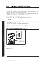
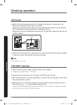
LED Display
1
When resetting the power supply, the FCU interface module will not respond to the
upper level communication for up to 10 minutes.
When the communication with lower level (e.g.: between FCU interface module and FCU
KIT) is detected as valid communication, Y-GRN LED will blink.
(Please wait until the communication between and FCU interface module and the FCU KIT
becomes normal.)
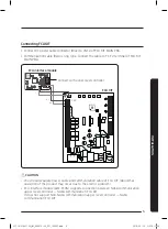
CN4
CN3
RED
CN2
BLK
R2
R1
YEL
RED
Y-GRN
YE
L
RE
D
Y-
GRN
LED
2
When the communication with upper level (e.g.: between DMS and FCU interface module)
is detected as valid communication, RED LED will blink.
NOTE
• YEL LED is not in use.
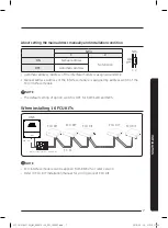
7-SEGMENT indication
1
When initializing power supply, program code will be indicated.
y
y
Exmaple of program code: 17 89 A3 16
2
Then tracking of FCU KIT will be on progress, and
will be indicated.
3
After tracking is done, communicating address of FCU KIT will be indicated in order when
the communication is normal.
4
When there is no communication between FCU KIT and FCU interface module for more
than 3 minutes,
↔
will be indicated alternatively.
y
y
Check the communication cable connection between FCU KIT and FCU interface module,
and reset the power of FCU interface module.
Checking operation
@FCU AIM-F10N_IM_06087A-00_EN_160307.indd 8
2016-03-15 오후 5:11:54