background image

E-

152

System Settings (Continued)

6

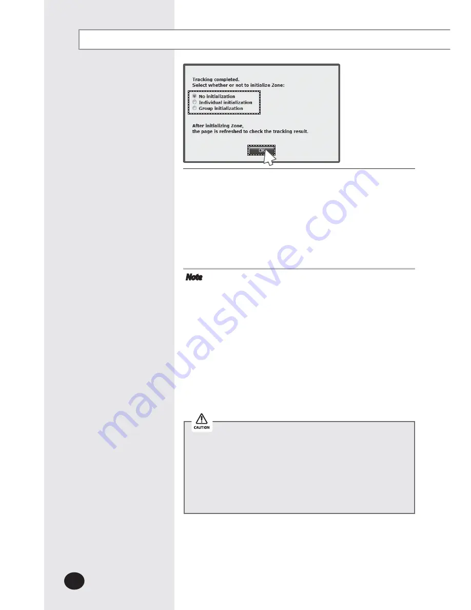
Tracking completed message will appear.  
Select Zone initialization mode you want and click [OK].

X


Not initialize:  No zone information initialization will be 

made.

X


Initialize individually:  Initialize zone information as 

individual mode.

X


Initialize by group:  Initialize zone information as group 

mode.

Note


X

If tracking is executed successfully while NEW is set 
as communication mode for each channel, virtual 
OnOff controller will be assigned to each channel.


X

If there is no searched outdoor unit, OnOff controller, 
SIM/PIM, it is regarded as DVM tracking failure.


X

If there are devices which have same address, first 
searched device will be registered only.


X

The number of OnOff controller doesn't contain  
 the number of virtual OnOff controller that is used 
 in NEW communication.


X

Group initialization will not be applied to Hydro Unit, 
Hydro Unit HT and Single EHS.

X

If you execute tracking, system setting will be initialized. 

X

If tracking result does not match with actual installation  

 information, there can be critical error in additional  
 functions such as power distribution.

X

Make sure that tracking information matches to actual 

installation information after tracking. 

6

Summary of Contents for MIM-D01AN

Page 1: ...a Management Server2 5 MIM D01AN MIM D01AUN BACnet Gateway MIM B17BN MIM B17BUN LonWorks Gateway MIM B18BN MIM B18BUN Air Conditioner user manual imagine the possibilities ThankyouforpurchasingthisSamsungproduct ...

Page 2: ...with a pointed thing X Do not pull or bend the product cable excessively X Do not use the product for other purpose X Do not spray an insecticide or other combustible things on the product X Do not clean the product with benzene solvents or other chemicals X Do not give a shock to the product or disassemble it by yourself X N utilisezpasdegazinflammableàproximitéduproduit X Nerenversezpasd eaudans...

Page 3: ...ION 162 X CHECKING INDOOR OUTDOOR UNIT INFORMATION 164 X CHECKING DMS2 5VERSION 165 X DATA BACKUP SETTING 169 X CHECKING ERROR INFORMATION 170 X RESET PASSWORD 171 X BUTTON LOCK 172 X SAFETY HALT 173 X TROUBLESHOOTING 174 X SPECIFICATIONS 176 X LICENSE 177 Note X The contents and pictures used in this user manual may be changed without advance notice for the functional reinforcement and improvemen...

Page 4: ... Level Controller When a separate upper level controller S NET series is used a number of DMS2 5 can be controlled with one central management system X Data Storage The DMS2 5 has its own database built in therefore trouble history indoor unit installation information and power distribution data can be saved and retrieved X Large Scale Management At most 256 indoor units can be connected to one DM...

Page 5: ...roller A device that controls 16 groups of the DVM air conditioner A central control device of a DVM system which is located between a DMS2 5 and an outdoor unit X AHU Air Handling Unit Executes heat exchange between air and cooling unit using central air conditioning duct method X ERV Energy Recovery Ventilator Ventilating system using heat recovery function Terms ...

Page 6: ...ews on the bottom and separate the bottom cover from DMS2 5 Then check cable connection part Name Description Power Turns blue when the power is supplied CPU Alive Blinks in orange with 1 second intervals during normal operation Ethernet Linked Turns green during normal connection Ethernet Active Blinks in orange during normal transmission reception COM1 5 TX Blinks in green during normal transmis...

Page 7: ...t DMS2 5 RS485 Communication terminal Connect for RS485 communication with devices such as OnOff Controller Outdoor unit COM1 COM5 Cable tie groove Arrange cables connected to DMS2 5 LAN Terminal Connect LAN cable Serial Terminal Service agent checks error status SD Card Socket Socket for sub memory SD or MMC Sub memory is for DMS2 5 program update and set information saving PurchaseSDcardseparate...

Page 8: ...nits per each communication channel of the DMS2 5 If the number of connected outdoor unit increases it may take long time for tracking Max 30 minutes PM 05 45 OnOff controller DMS2 5 Internet WebClient RMSSenter S NET3 TCP IP R5485 DVMSeries OutdoorUnit Max256 Indoorunits SIM PIM Powermeter Before Use System Configuration Touch Centralized controller ...

Page 9: ...ublic IP you must set Enable public IP as Enable from the menu System Settings System environment setting Private IP range 10 0 0 0 10 255 255 255 172 16 0 0 172 31 255 255 192 168 0 0 192 168 255 255 Computer Settings for DMS2 5 Connection X For devices that support new communication you must set the communication mode of the channel to NEW from System settings Tracking menu Set of Indoor outdoor...

Page 10: ...rror occurs it sends trouble history to e mail saved in DMS2 5 XSome functions available on DMS2 5 web page may not be functional at BACnet Gateway and Lonworks Gateway For detailed function refer to the installation manual or contact Samsung Electronics SaveTrouble History The DMS2 5 receives manages setting and control data from the upper level controller and sends the received data to the lower...

Page 11: ... RC Disable RC Cond RC Fan speed Auto Low Mid High Turbo Air flow None Vertical Horizontal All ERV operation mode Auto HeatEx ByPass Sleep ERV Fan speed Low High Turbo Weekly Repeat Maximum 10 events per day Daily Repeat Maximum 70 events The schedule function of the DMS2 5 can be set through the Web or using the upper level controller 1day Everyday Every week schedules can be set XEach schedule c...

Page 12: ...oor units The DMS2 5 saves at most 1 year of data After a year the oldest data is deleted and the latest data is saved This data can be checked through the built in Web page of the DMS2 5 or by S NET 3 Save Integrated Power Distribution Data Main Function Continued PM 05 45 OnOff controller DMS2 5 Internet WebClient RMSSenter S NET3 TCP IP R5485 DVMSeries OutdoorUnit Max256 Indoorunits Powermeter ...

Page 13: ...ours can also be divided into 2 sections A B A 3 sections A B C A or 4 sections A B C D A X DMS2 5 shows the result of the power distribution for each section you set Inputmanually Whensetting2sections 3sections and4sections Time Segmentation If communication error occurs between DMS and the lower level controllers actual power consumption and the result of power distribution value may not be same...

Page 14: ...DMS2 5 and other devices such as outdoor units control devices 2 Execute tracking X DMS2 5 communicates with outdoor unit and brings information about installed indoor unit and outdoor unit X After tracking you can use indoor unit control and other menu X For tracking refer to System Settings Tracking Refer to page 148 152 Connecting OnOff controller outdoor unit Starting DMS2 5 Access to DMS2 5 L...

Page 15: ...rning popup message will appear as shown This message appears since DMS2 5 used the certificate of its own so it will not appear if DMS2 5 certificate is registered on web browser DMS2 5 certificate must be registered because the message will appear every time and it is not safe for security if it is not registered Also it should be registered to all PCs that are connecting to DMS2 5 You must stop...

Page 16: ...sted Root Certification Authorities and click Import C Click Next D Select Browse and find DMS2 5 certificate and click Next DMS2 5 certificate can be downloaded from System environment setting Starting DMS2 5 Continued ...

Page 17: ...E Select Place all certificates in following drive and click Next F Click Finish and click Yes when security warning appears 3 Click Run and continue installation X Access to DMS2 5 again after installation ...

Page 18: ...X To edit user authorization refer to System Settings User authorization management Refer to page 112 Note X Onlyauthorizeduserscanaccesstowebpage X Fewerthan5concurrentusersarerecommended becauseconnectionspeedmayslowdown X DMS2 5managershouldchangeIDandpasswordfor securityandmanagement Refertopage110 X Logout Tologout click LOGOUT onthetopofthe menu Silverlight will run normally with Windows 7 o...

Page 19: ...n 1 When the screen above appears ask for manager X Depending on control authorization setting there can be a user who does not have control authorization X Above screen will appear when the logged in user does not have control authorization ...

Page 20: ...Display Remotecontroller Controllingrange Indoor unit display icon DI Digital Input display icon ERV display icon DO Digital Output display icon AHU display icon Hydro Unit HT display icon ERV PLUS display icon FCU Kit display icon Hydro Unit Single EHS display icon DVM CHILLER display icon Fresh duct display icon E 20 ...

Page 21: ...dfunctions suchasSleepmode Energysavingfunction areselectedthroughwired wirelessremotecontrollersorindoorunitpanel setoperationmodeontheremotecontrollersandDMS2 5maybedisplayed differently Also whencontrollingbyDMS2 5 additionalfunctionswillbe canceled XDependingonthemodelofindoorunit Horizontal Allairflowdirectioncontrol maynotbepossible Inthiscase verticalorfixedflowwillbedisplayeddepending onin...

Page 22: ...screen will appear when you log in to DMS2 5 web page 2 Select an indoor unit to control X Check the indoor unit status through status display window X When the selected indoor unit is switched on the remote controller panel will be automatically activated 3 Turn the indoor unit on by clicking X Remote controller panel will be activated 1 Statusdisplaywindow 3 2 ...

Page 23: ...d temperature in Fan mode X When the operation mode of an indoor unit is Cool or Dry mode you cannot set the desired temperature lower than lower limit temperature if lower limit is enabled X When the operation mode of indoor unit is Heat mode you cannot set the desired temperature higher than upper limit temperature if upper limit is enabled 6 Select the fan speed X You can select Auto Low Mid an...

Page 24: ...nable RC Disable RC and Cond RC X When selecting Disable RC indoor unit control by wired wireless remote controller and indoor unit panel is not possible Indoor unit control is only available in DMS2 5 web page X Click when you want to use wired remote controller in each room 9 Select SPI setting X You can set SPI through button activation non activation E 24 8 7 9 10 11 12 ...

Page 25: ...Heating discharged temperature can be set in the range of 30 C 68 F 43 C 109 F 12 Select Control Discharge Temp X You can enable disable button to decide whether to use discharge temperature adjustment Note Whenfilterwarningsignisdisplayedonindoorunitstatuswindow Selecttheindoorunitandclick Resetfilter Filterwarningwillbereleased X Makesurethateachindoorunitmustbeturnedontocontrol X Selectingremot...

Page 26: ...its 1 Click Control and Monitoring when DMS2 5 web page menu screen appears X Control and Monitoring screen will appear when you log in to DMS2 5 web page 2 Select an indoor unit to control X Check the indoor unit status through status display window X When the selected indoor unit is switched on the remote controller panel will be automatically activated 1 2 Statusdisplaywindow ...

Page 27: ...de with no limits Note X OperationmodelimitssettingisnotavailableinERVandDVMCHILLER X If you set the operation mode limit DMS2 5 will automatically change the operation mode limit setting of all the indoor units connected to same outdoor unit X If the indoor unit is cooling only model you cannot set the operation mode limit to heatonly ...

Page 28: ...DMS2 5 web page menu screen appears X Control and Monitoring screen will appear when you log in to DMS2 5 web page 2 Select an indoor unit to control X Check the indoor unit status through status display window X When the selected indoor unit is switched on the remote controller panel will be automatically activated Setting Lower UpperTemperature Limit of an Indoor Unit 2 1 Statusdisplaywindow ...

Page 29: ...desired temperature higher than the upper temperature limit 4 Set lower temperature limit by pressing S and T X You can set lower temperature limit by clicking Cool lower limit X Lower temperature limit can be set in the range of 18 C 64 F 30 C 86 F X When indoor unit is operating in Cool or Dry mode and the low temperature limit is applied you cannot set the desired temperature lower than the low...

Page 30: ...utomatically activated Note X TocontrolAHU referto the Controllinganindoorunit steps Refertothepage20 23 X AHU sfanspeedisfixedashigh X YoucannotsetairflowdirectionofAHU X TosettheoperationmodelimitofAHU refertothe Indoorunitoperationmode limit steps Refertothepage24 25 X Tosetthelower uppertemperaturelimitofAHU refertothe Settinglower upper temperaturelimitofindoorunit steps Refertothepage26 27 X...

Page 31: ...nd Monitoring when DMS2 5 web page menu screen appear X Control and Monitoring screen will appear when you log in to DMS2 5 web page 2 Check the current status of a Fresh duct X Check the status of a Fresh duct through the status display window X When the selected Fresh duct is switched on the remote controller panel will be automatically activated 1 2 Statusdisplaywindow ...

Page 32: ...When the selected Fresh duct is switched on the remote controller panel will be automatically activated 3 Turn the Fresh duct on by clicking X Remote controller panel will be activated 4 Set cooling heating discharge temperature by clicking S and T X When the Fresh duct is in Cool mode the Fresh duct can be set as cooling discharge temperature and when the Fresh duct is in Heat mode the Fresh duct...

Page 33: ...ct control Refer to page 22 25 X The fan speed of a Fresh duct is fixed as High X Setting air flow direction of a Fresh duct is not available X Refer to the Indoor unit operation mode limit for Fresh duct operation mode limit Refer to page 26 27 E 33 ...

Page 34: ...n appears X Control and Monitoring screen will appear when you log in to DMS2 5 web page 2 Check current status of ERV X Check the status of ERV through the status display window X When the selected ERV is switched on the remote controller panel will be automatically activated Monitoring ERV Operation Status 2 Statusdisplaywindow 1 Control and Monitoring Continued ...

Page 35: ...d Monitoring when DMS2 5 web page menu screen appears X Control and Monitoring screen will appear when you log in to DMS2 5 web page 2 Select an ERV to control X When the selected ERV is switched on the remote controller panel will be automatically activated 3 Turn ERV on by pressing X The remote controller panel will be activated 1 3 2 ...

Page 36: ...g Enable RC indoor unit control by wired wireless remote controller is not possible Indoor unit control is only available in DMS2 5 web page X Click when you want to use wired remote controller in each room Note X WhenfilterwarningsignisdisplayedonERVstatus window SelecttheERVandclick Resetfilter Filterwarningwillbe released X MakesurethatERVmustbeturnedontocontrol X Selectingremotecontrollerandfi...

Page 37: ... and Monitoring when DMS2 5 web page menu screen appears X Control and Monitoring screen will appear when you log in to DMS2 5 web page 2 Check the current status of ERV PLUS X Check the status of ERV PLUS through the status display window X When the selected ERV PLUS is switched on the remote controller panel will be automatically activated 1 2 Statusdisplaywindow ...

Page 38: ...the selected ERV PLUS is switched on the remote controller panel will be automatically activated 3 Turn the ERV PLUS on by clicking X Remote controller panel will be activated 4 Select the operation mode X You can select Auto Cool Off and Heat mode Note X Refer to the Controlling ERV for ERV PLUS control Refer to page 35 36 X Refer to the Indoor unit operation mode limit for ERV PLUS operation mod...

Page 39: ...cted Hydro unit is switched on the remote controller panel will be automatically activated X Hydro unit does not support multiple selection with other devices and you can only control and monitor the Hydro unit individually When you select Hydro unit while multiple devices are already selected previously selection of multiple devices will be canceled 3 Turn the Hydro unit on by clicking X Remote c...

Page 40: ...e displayed Control and monitoring status of current temperature desired temperature operation mode Heat upper limit and Cool lower limit will be changed depending on the type of temperature control X Room You can only control Cool and Heat mode X Water out You cannot adjust the desired temperature in Auto mode 6 4 5 8 9 11 12 10 7 Control and Monitoring Continued ...

Page 41: ...irect hot water only when the operation mode is on Auto or Heat mode 10 Select desired temperature for hot water by clicking S T 11 Select desired operation mode for hot water X Select the operation mode from Eco Standard Power 12 Select DHW upper temperature limit by clicking S T Note X Since the Hydro Unit and Hydro Unit HT does not have any filters filter monitoring and filter reset is not avai...

Page 42: ... switched on the remote controller panel will be automatically activated X Hydro Unit HT does not support multiple selection with other devices and you can only control and monitor the Hydro Unit HT individually When you select Hydro Unit HT while multiple devices are already selected previously selection of multiple devices will be canceled 3 Turn the Hydro Unit HT on by clicking X Remote control...

Page 43: ...be displayed Control and monitoring status of current temperature desired temperature operation mode Heat upper limit and Cool lower limit will be changed depending on the type of temperature control X Room You can only control Heat mode X Water out You can only control Auto and Heat mode You cannot adjust the desired temperature in Auto mode 6 4 5 8 7 9 11 12 10 ...

Page 44: ...tion mode for hot water X Select the operation mode from Eco Standard Power Force 12 Select DHW upper temperature limit by clicking S T Note X Since the Hydro Unit HT does not have any filters filter monitoring and filter reset is not available X HydroUnitHTdoesnotsupporttemperaturein Fahrenheit Controlling Single EHS 1 Basic control operating procedures are the same as Hydro Unit and others are a...

Page 45: ... the current status of DI and DO device 3 Monitor the device through the control panel Note X EnteringOnOffbecomesimpossibleforDIdevice X EnteringOnOffbecomespossibleforDOdevice X Enteringcontrolvaluebecomesimpossiblefor DI DOdevice X YoucancontrolandmonitorDI DOwhichbuilt in DMS2 5 However DI1 2andDO1 2 9 10are excluded fromcontrollingandmonitoringbecausetheyare usedfortheinternalfunctionofDMS 1 ...

Page 46: ...reen will appear when you log in to DMS2 5 web page 2 Select DO device to control when control and monitoring screen appears X Check the status of DI or DO device 1 3 3 Turn DO device on by clicking ON OFF button on the control panel Note RemotecontrollersettingisnotpossibleforDI DOdevice Control and Monitoring Continued 2 ...

Page 47: ...to DMS2 5 web page 2 Select FCU to control when control and monitoring screen appears X Check the status of an indoor unit through status display window X When the selected indoor units are switched on the remote controller panel will be automatically activated 3 Turn the selected indoor units on by clicking X Remote controller panel will be activated 1 3 2 ...

Page 48: ...rol Refer to page 22 25 X Refer to the Indoor unit operation mode limit for FCU Kit operation mode limit Refer to page 26 27 X Refer to Setting Lower Upper Temperature Limit of an Indoor Unit for FCU Kit temperature limits Refer to page 28 29 Control and Monitoring Continued ...

Page 49: ... DMS2 5 web page 2 Select DVM CHILLER to control when control and monitoring screen appears X Check the status of an indoor unit through status display window X When the selected indoor units are switched on the remote controller panel will be automatically activated 3 Turn the selected indoor units on by clicking X Remote controller panel will be activated 1 2 3 ...

Page 50: ... Select Quiet function X You can enable disable button to select Quiet function 8 Select Forced Fan function X You can enable disable button to select Forced Fan function 9 Select Demand level by clicking S T X You can select Demand level in range of 50 100 Note X Power desired temperature operation mode operation pattern Water Law Quiet function Forced Fan function Demand function can be controll...

Page 51: ...ally activated Note X Whenusersselectmultipledevices BasicControl willbedisplayed onthescreen Thisiswhendifferenttypesofmultipledevicesareselected X Thecurrentstatusoflastselectedindoorunittypedevices Indoorunit AHU Freshduct willbedisplayedonthe Indoorcontrol X ThestatusoflastselectedERVtypedevices ERV ERVPLUS willbedisplayed onthe VentilationControl X Thelistoftheselectedmultipledeviceswillbedis...

Page 52: ...d Monitoring screen will appear when you log in to DMS2 5 web page 2 Check the status of the selected devices X Check the status of an indoor unit through status display window X When the selected devices are switched on the remote controller panel will be automatically activated 3 Turn the selected devices on by clicking X Remote controller panel will be activated 3 ...

Page 53: ...ode X When the operation mode of an indoor unit is in Cool or Dry mode you cannot set the desired temperature lower than lower limit temperature if lower limit is enabled X When the operation mode of an indoor unit is in Heat mode you cannot set the desired temperature higher than upper limit temperature if upper limit is enabled 5 Select the operation mode X You can select Auto Cool Dry Fan and H...

Page 54: ...beactivated X Whencontrollinganindoorunit ERVdevices ERV ERVPLUS cannotbecontrolled X WhencontrollingERVdevices Indoorunit Indoorunit AHU Freshduct cannotbecontrolled X YoucanselectpowerOnOff DisableRC Resetfilter IndoorControl Desiredtemp operationmode fan speed andERVControlinthe Basiccontrol X PowerOnOff DisableRCandResetfilterarecontrolled toallthedevices X Whenselectingmultipledevices thelist...

Page 55: ... when DMS2 5 web page menu screen appears X Control and Monitoring screen will appear when you log in to DMS2 5 web page 2 Click Install Info tab at the bottom left of the screen 3 Check installation status of currently connected device in the installation information tab X You can check installation information by pressing and buttons 1 3 2 ...

Page 56: ... X Control and Monitoring screen will appear when you log in to DMS2 5 web page 2 Select a device you want to view control history and power consumption 3 Click View control history power consumption tab and wait for a while X Control history and power consumption information are received from DMS2 5 X Data receiving message will appear on the bottom right of the tab Control and Monitoring Continu...

Page 57: ...powercontroland remotecontrollerusagestatus X Operationmode desiredtemperature airflowandfan speedcontrolshowsyouthecontrolledtimeandtype ofcontrolonly X IfSIM PIMisnotinstalled powerconsumption informationmaynotbecorrect X Powerconsumptioninformationisdisplayedonly whenSIM PIMisinstalled X IfSIM PIMisremoved valuemeasuredwith SIM PIMwillbedisplayed 4 ...

Page 58: ...ect OnOff controller its subordinate outdoor unit which has the earliest address will be selected X If you select an outdoor unit all the information of the module that are connected to the selected outdoor unit will be displayed X If you select indoor unit upper outdoor unit will be selected 4 Cycle information of selected outdoor unit and subordinate indoor units X If the status of outdoor unit ...

Page 59: ... Click Control and Monitoring Indoor unit usage restriction when DMS2 5 web page menu screen appears 2 Press Edit button 3 Set the limit mode X You can select Cool only Heat only or None For cooling only indoor unit you can select cool dry and fan modes only For heating only indoor unit you can select heat and fan modes only 1 3 ...

Page 60: ...llingitincontrolmode X SinceHydrounitHTdoesnotsupportCoolmode controlmodeforHydrounitHT canonlybesetas Heatonly or None Control and Monitoring Continued X When you set the operation mode limit and if the outdoor unit is HP Heat pump type DMS2 5 will automatically change the operation mode limit setting of all the indoor units connected to same outdoor unit X If the indoor unit is cooling only mode...

Page 61: ...et the Lower temperature limit in Cool mode and Upper temperature limit in Heat mode according to room temperature If the temperature control of Hydro unit is set as Water out you can set the Lower temperature limit in Cool mode and Upper temperature limit in Heat mode according to water out temperature X For Hydro unit HT if the temperature control is set as Room you can set the Upper temperature...

Page 62: ...de number and status 3 You can check detailed information on trouble history by selecting the item in the list Note X DMS2 5savesmaximum1024troublehistories Ifthenumberofhistoryexceeds1024 DMS2 5will deletetheoldesthistoryfirst X Ifthesamecodetroubleisdetectedrepeatedlyinthe samedeviceonthesameday troublehistorywillbe shownas1case Ifitoccursmorethan2times Resolutiontime maychangeeverytimeyoucheck ...

Page 63: ... Control and Monitoring Trouble history when DMS2 5 web page menu screen appears 2 Enter the time period you want to check X Enter year month day in order 3 Click Search X You can check address device type occurrence time resolution time code number and status in the entered period 4 You can check detailed information on trouble history by selecting the item in the list 2 4 3 ...

Page 64: ...Control and Monitoring Trouble history when DMS2 5 web page menu screen appears 2 Select trouble history you want to delete 3 Click Delete X Click OK from the confirm window Selected trouble history will be deleted Deleting theTrouble History 1 2 3 ...

Page 65: ...ntrolled at set value X If the value was set manually on DMS2 5 outdoor unit will always operate at set value Note X Outdoorunitcontrolissupportedoncertainmodelsonly andthe Outdoorunit controlpage onlyappearsonthosesupportedmodels 1 Click Control and Monitoring Occupied Vacant room control when DMS2 5 web page menu screen appears 2 Click Edit and select the desired setting for Mode Desired tempera...

Page 66: ... indoor unit which is controlled by DMS2 5 and subordinate controller 3 You can check operation status by entering date X Enter year month day then click Search You can check control history that occurred on the entered date 4 You can check detailed control history which is controlled by the command by pressing control history in the list Note DMS2 5savestheinformationofoperationhistoryfor180 days...

Page 67: ...lization reorganizes connected indoor unit based on RMC address X After group initialization indoor units are displayed as one device when upper zone is selected in the Control and Monitoring screen X When editing zone after group initialization moving in group is only allowed X After group initialization subordinate devices cannot be moved individually to the other zone Note X Onlytheuserwhohasau...

Page 68: ...l and monitor zone has 5 sign 3 Click Save to save X The user of currently selected zone is selected in the screen XYoushouldsettheauthorizationforcontrollingandmonitoringthezonewhenthe userisadded XIfyoudonotsettheauthorizationforzoneafteraddingauser thezonewillnotbe displayedeveniftheuserloggedin XSettingtheuserauthorizationisvalidonlyforthezonedisplayedonthescreen Ifyou selecttheotherzonesettin...

Page 69: ...nagement Zone Setting Edit when DMS2 5 web page menu screen appears X Same screen will be displayed even if you press Zone management only 2 Click Zone Edit X Zone edit screen will be displayed Zone Setting Edit Zone Edit 2 ...

Page 70: ...plowerthantheuserselected Youcannotcreateazoneunder5stepsinzoneedit Remove Removeselectedzone Iftheselectedzoneincludesdevice thedevicewillmovetothetopstep Moveup Moveuptheselectedzoneorindoorunit Movedown Movedowntheselectedzoneorindoorunit Movetoupper level Movetheselectedzoneorindoorunittotheupperlevel Rename Renametheselectedzoneorindoorunit Youcanusemaximum16letters Cut Cuttomovetheselectedzo...

Page 71: ...agesAHUkit ingeneralzone 䯼Theusercancreateanddelete 䯼Itwillbedisplayedassingledevicein thecontrolandmonitoringscreen and itcanbecontrolledassingledevice 䯼Youcannotmovesubordinatedevice totheotherzone Group initialization mode General 䯼Virtualgroupwhichissetand managedbytheuser 䯼Theusercancreateanddelete Group 䯼Virtualgroupwhichismanagedby installationaddress notby RMC address 䯼Theusercannotcreatea...

Page 72: ...e when the schedule setting screen appears 4 Select schedule period you want by clicking calendar X If you select No limit when setting end date it means there is no period and it displays Dec 31st 9999 To set the end date remove the check of No limit or select calendar icon which is on the right side of date 5 To set an exception date in the schedule period click Add and select date month day you...

Page 73: ...E 73 6 To cancel the added exception date select the exception date it 5 and click Delete X Maximum 365 exception dates can be saved 6 ...

Page 74: ...of all the connected devices will be displayed X You can register a schedule for DMS DO as well X You cannot select DVM CHILLER and other devices simultaneously 8 To cancel the selected device select 5 the device again and click Delete 7 8 Schedule Continued ...

Page 75: ...ote controller or indoor unit panel in each room is not possible Cond RC ON by OnOff controller DMS2 5 Controlling indoor unit using wired wireless remote controller or indoor unit panel in each room is possible OFF by OnOff controller DMS2 5 Controlling indoor unit using wired wireless remote controller or indoor unit panel in each room is not possible X Click Add to add event X To delete event s...

Page 76: ...eedisalways setto Auto XWhenyouselectsleepmodeamongERVmodes Mid fanspeedisonlyavailable XIfthetrackingisnotcompleted schedulesettingisnot possible Touseproperschedulefunction makesureto completetrackingwithinstallationengineer X Off operation works only with ERV PLUS X CoolStorage and HotWater modeworksby DVMCHILLERonly XTheTurbofanspeedisavailableonlyinthedevices thatsupporttheTurbofanspeed Forth...

Page 77: ... want by clicking calendar X If you select No limit when setting end date it means there is no period and it displays Dec 31st 9999 To set the end date remove the check of No limit or select calendar icon which is on the right side of date 5 To set an exception date in the schedule period click Add and select date month day you want X Select an exception date on the calendar window Creating new sc...

Page 78: ...E 78 6 To cancel the added exception date select the exception date 5 and click Delete X Maximum 365 exception dates can be saved 6 Schedule Continued ...

Page 79: ...elect a device to apply X The list of all the connected devices will be displayed Select a device and click OK X You can only select one device 8 To cancel the selected device select 5 the device again and click Delete 7 8 ...

Page 80: ...less remote controller or indoor unit panel in each room is not possible Cond RC ON by OnOff controller DMS2 5 Controlling indoor unit using wired wireless remote controller or indoor unit panel in each room is possible OFF by OnOff controller DMS2 5 Controlling indoor unit using wired wireless remote controller or indoor unit panel in each room is not possible X Click Add to add event X To delete...

Page 81: ...ired temperature setting depending on control type and mode X Donotinputthedesiredtemperaturewhenthe operationmodeissetto Auto X Donotturnonthepowerfordirecthotwaterwhenthe operationmodeissetto Cool X Schedulesettingisnotavailablewhenthetrackingis notcompleted Tousetheschedulefunctionnormally completethetrackingwiththeinstallationexpert X When Thermostat 1 or Thermostat 2 is ON the desired tempera...

Page 82: ...enu screen appears 2 Select the schedule to edit X For the currently operating schedule you can only check it 3 Click Edit X Edit schedule when the schedule edit screen appears X Editing schedule method is same as Creating New Schedule Refer to page 72 76 1 2 3 Schedule Continued ...

Page 83: ...le is in stop status If you want to delete schedule which is currently applied stop applying the schedule first 1 3 2 Applying schedule 1 Click Schedule Schedule setting when DMS2 5 web page menu screen appears 2 Select the schedule you want to use 3 Use schedule functions by clicking Run and Stop X To apply the selected schedule click Run X To stop the selected schedule click Stop Note Tostopalls...

Page 84: ...ge menu screen appears 2 Select a date to check and then click Search X Only executed schedules can be searched 3 You can check detailed setting by clicking the schedule name Note DMS2 5savestheinformationorschedulecontrolhistory for180days However itvariesdependingonsavingspaceofDMS2 5 2 3 Schedule Continued ...

Page 85: ...you can check up to 365 days of watt hour meter value 3 Click Search X Inspection result will be displayed depending on set period and searching condition X You can check power consumption only when watt hour meter is connected If watt hour meter is not connected you can check operating proportion by indoor unit only 4 Click Save as Excel X Searched inspection result will be saved as MS Excel file...

Page 86: ...et date when inspection result screen appears X Select year month day in order X Based on DMS2 5 time You can check up to 365 days of inspection results 3 Enter power consumption value during the period X Virtual channel is value which is set in channel setting by indoor unit 4 Click Calculate X Power consumption by indoor unit during the period will be displayed 1 3 4 2 EHP Power Consumption Insp...

Page 87: ...ch other X If you want to save the consumption result for selected period as MS Excel file click Save as Excel X Click Calculate to go back to inspection result screen Note X Fordatamanagement itisrecommendedtosave indoorunitinspectionresultperiodically X Powerconsumptioninspectionresultisforreference onlyandshouldnotbeusedforofficialfinancial transactions ...

Page 88: ...nd enter time of section B and section C when selecting 3 sections and enter time of section B section C and section D when selecting 4 sections X Correct format of time is HH MM Ex 4 30 in the afternoon 16 30 4 Click Save X Set power section will be saved in DMS2 5 X If you do not click Save changed setting will not be saved Note X Ex Whenselecting2sections A B A IfthebordertimebetweenAandBis08 0...

Page 89: ...our meter X You can use maximum 16 letters X The range of CT proportion value is positive number from 1 to 5000 X CT proportion setting is required only when the meter type is electricity 4 Click Save X Set the meter information will be saved in DMS2 5 X If you do not click Save changed setting will not be saved X Watt hour meter value shows actual value of currently connected watt hour meter Watt...

Page 90: ...y screen appears X Enter year month day in order X Based on DMS2 5 time you can check up to 365 days of meter value history 4 Click Search X Meter value history of set period will be displayed 5 Click Excel X When you click the Excel button meter value of all SIM PIM throughout the selected dates will be saved as MS Excel file 2 1 3 4 5 ForPIM channelstatusshouldbesetas Enable inorderto savethemet...

Page 91: ...virtual channels can be set Virtual channel is written in 24 31 1 16 format address Ex 24 1 25 2 31 8 2 Click Edit when the setting and checking virtual channel screen appears 3 Set the name of virtual channel X You can use maximum 16 letters 4 Click Save X Set virtual channel name will be saved in DMS2 5 X If you do not click Save changed setting will not be saved 3 1 4 2 ...

Page 92: ...ge menu screen appears 2 Click Edit when the setting channel by indoor unit screen appears 2 1 Some functions available on DMS2 5 web page may not be functional at BACnet Gateway and LonWorks Gateway For detailed function refer to the installation manual or contact Samsung Electronics EHP Power Consumption Inspection Continued ...

Page 93: ... bringing indoor unit s power from outdoor unit set the Outdoor unit SIM channel information only Outdoor unit SIM channel is referring to watt hour meter which is connected to outdoor unit X When bringing indoor unit s power from the other device not from outdoor unit set the Outdoor unit SIM channel and Indoor unit SIM channel information Indoor unit SIM channel is referring to watt hour meter w...

Page 94: ...nded to execute power distribution using SIM PIM 7 Set indoor unit to execute power distribution X If you do not set the watt hour meter information the power distribution result of the indoor unit will be displayed as 0 8 Click Save X Set channel information will be saved in DMS2 5 X If you do not click Save changed setting will not be saved XInformationofwatt hourmeterconnectedtoindoor outdoorun...

Page 95: ...by date when Checking indoor unit operating time screen appears X Select year month day in order X Based on DMS2 5 time you can check up to 365 days of operation time 3 Click Search X Operation time will be displayed depending on set period and condition 4 Click Save as Excel X Searched operation time result will be saved as MS Excel file Note Fordatamanagement itisrecommendedtosaveindoor unitoper...

Page 96: ... of indoor unit is higher than 29 C control indoor unit as cool mode Yes will be displayed when the indoor unit s current temperature is higher than 29 C No will be displayed when the indoor unit s current temperature is lower than 29 C 2 Click New when setting control logic screen appears X Setting screen is composed of 4 categories Name time Set the name and time period days time to apply of con...

Page 97: ... use maximum 16 letters 4 Set period day and time in control logic screen X Select year month day in order X Select a day to run during the control period X Control logic will be applied only when period day and time are united X If you select Daily in day selection control logic will run regardless of day 3 4 ...

Page 98: ...perature of indoor unit X Arithmetic It means 2 devices are connected by arithmetic operator Ex Desired temperature of indoor unit 1 Desired temperature of indoor unit 2 X Function It means several devices are using as value of function Ex Average Current temperature of Indoor unit 1 Current temperature of Indoor unit 2 Current temperature of Indoor unit 3 Control Logic Management Continued ...

Page 99: ... False Controlimpossible Limitoperationmode None Coolonly Heatonly ERV PLUS Power On Off Outdoortemp Number Controlimpossible ERVmode Auto HeatEX Bypass Sleep ERVfanspeed Low High Turbo Operationmode Auto Cool Heat Off RCusage EnableRC DisableRC Cond RC Errordetection True False Controlimpossible Limitoperationmode None Coolonly Heatonly Type Item Value Remarks Fresh duct Power On Off Operationmod...

Page 100: ...LLER Power On Off Currenttemp Number Controlimpossible Desiredtemp Number Outdoortemp Number Controlimpossible Operationmode Cool CoolStorage Heat HotWater RCusage EnableRC DisableRC Cond RC Errordetection True False Controlimpossible Type Item Value Remarks FCUKit Power On Off Currenttemp Number Controlimpossible Desiredtemp Number Operationmode Auto Cool Fan Heat Fanspeed Auto Low Mid High RCusa...

Page 101: ... item of left factor Ex1 Factor Power of indoor unit 1 Factor of standard value Power of indoor unit 2 Ex2 Factor Current temperature of indoor unit 1 Factor of standard value Average current temperature of indoor unit 1 and 2 13 Select duration time usage X Duration time means the time which the comparing conditions satisfy True X The duration time can be set from 1 to 60 X If you select duration...

Page 102: ...AND if all the input items each should be True X Select OR if just 1 input item needs to be True X Compound factor has priorities in order For example if you set OR AND in order it means input item 1 OR input item 2 AND input item 3 After selecting the compound factor you must tick the check box on the left side 15 Select Select a factor in the Output list 15 Control Logic Management Continued ...

Page 103: ...e factor can be set for the left factor of output Single factor It means 1 device Ex Desired temperature of indoor unit 17 Click Select X List of device which can be selected will be displayed 18 Select the device to use as factor 18 16 17 ...

Page 104: ...pply X If you do not click Apply changed setting will not be saved 21 Select command value X The value may vary depending on the detailed item of selected factor X You can select value of selected item or new factor X You can set single factor arithmetic factor and function factor 20 19 21 Control Logic Management Continued ...

Page 105: ... will be saved in DMS2 5 X If you do not click Save changed setting will not be saved Note X Controllogicinputitemsconsistoffactor comparisonoperator standardvalue anddurationtime X Youcanenterupto3inputitemsofcontrollogic andtheitemscanbeconnected withcompoundfactor X Outputitemofcontrollogicconsistsoffactorandcommandvalue X Youcanenterupto20outputitemsofcontrollogic X Youcancreateupto256controll...

Page 106: ...nu screen appears 2 Select control logic when control logic screen appears 3 Click Edit Delete Copy X To edit control logic refer to Setting control logic steps Refer to page 96 105 X Click Delete to delete the selected control logic X Click Copy to copy the selected control logic 1 2 3 3 Control Logic Management Continued ...

Page 107: ... applied by clicking Apply X The selected control logic will not be applied by clicking Not apply Note X WhentheselecteddeviceisHydrounit HydrounitHTor SingleEHSandThermostat 1orThermostat 2isON thecontrollogicofthedesiredtemperature waterout temperatureandoperationmodecannotbecontrolled X When the selected device is Single EHS and the hot water thermostat is ON the control logic of the desired te...

Page 108: ...lect Year Month Day in order X Based on DMS2 5 time you can check of maximum 180 days of previous control history 3 Click Search X You can check only in daily unit 4 Select each items to check detailed contents of control history Note DMS2 5savestheinformationofcontrollogic managementcontrolhistoryfor180days However it variesdependingonsavingspaceofDMS2 5 1 3 4 2 Control Logic Management Continued...

Page 109: ...dition the password should contain both English letters and numbers X Name should be within 20 letters and description should be in 50 letters X Registration date will be input automatically as system date X Select authorization for the user from Admin Manager and Regular user Admin has all authorization and Manager Regular user has limited authorization 4 Click Save X Maximum of 256 users can be ...

Page 110: ...ption should be in 50 letters X Registration date is input automatically as system date Therefore you cannot edit registration date X Select authorization for the user from Admin Manager and Regular user Admin has all rights and Manager Regular user has some rights 4 Click Save X Modified user information will be saved in DMS2 5 Note X Userinformationcanbechangedonlywiththeadminaccount X Authoriza...

Page 111: ...kname to delete when user management screen appears X User information window will be displayed 3 Click Delete when the user delete window appears X Confirm window will pop up saying Do you want to delete the user 4 Click OK X Selected user information will be deleted in DMS2 5 Note Adminaccountcannotbedeleted 2 1 3 4 ...

Page 112: ... the user authorization management screen appears 3 Click Save after setting is completed 4 Click OK when Successfully done message appears X Changed user authorization information will be saved in DMS2 5 by clicking OK Note X Administrator Adminauthorization isallowedto accesstoallmenus X Youcannoteditauthorization menuaccess of administrator Admin 1 2 4 3 System Settings Continued ...

Page 113: ...page menu screen appears 2 Click Initialize when user management screen appears 3 Click OK when Successfully done message appears X User authorization information saved in DMS2 5 will be initialized by clicking OK Note Youcanrestoreuserauthorizationinformationasfactory settingbyusinginitializationfunction 1 2 3 ...

Page 114: ...a backup restoration when DMS2 5 web page menu screen appears 2 Click PC backup when DMS2 5 data backup restoration screen appears X Reading data from DMS2 5 Please wait message will appear X Depending on the size of the data backup time may vary It will usually take few seconds 1 2 System Settings Continued ...

Page 115: ...E 115 3 Click OK when Backup file is ready Click OK to download message appears 4 Click Save when File download window appears 3 4 ...

Page 116: ... day X The extension of the backup data files is dms X If you want to edit the file name use English alphabets or numbers only X File name should be less than 32 letters If the file name exceeds 32 letters proper restoration may not be possible 6 Click Close after completing the download Note BackupdataincludesDBdata settingdata datarelated indoor outdoorunitcontrolandvariouskindsofhistory data Th...

Page 117: ...ttings Data backup restoration when DMS2 5 web page menu screen appears 2 Click SD card backup when DMS2 5 data backup restoration screen appears X Reading data from DMS2 5 Please wait message will be displayed X Depending on the size of the data backup time may vary It will usually take few seconds 1 2 ...

Page 118: ...f the SD card is inserted or forbidden for writing Note BackupdataincludesDBdata settingdata datarelated indoor outdoorunitcontrolandvariouskindsofhistory data Theywillbebackedupinsingleunifiedfile X To use SD backup and restoration function properly SD card which is formatted in VFAT file system is required X If SD card is already inserted automatic backup function will be operated and everyday d...

Page 119: ...e menu screen appears 2 Enter the password of Admin account when DMS2 5 data backup and restoration screen appears X Data restoration function deals with the important data of the system To activate the function you should enter administrator s password 3 Click OK 4 Click OK when caution window appears 1 3 2 ...

Page 120: ... Click Browse X Select DMS2 5 data file to restore and then click Open O when File selection window appears 7 Check if the file route and file name are correctly entered in the text box and then click Upload System Settings Continued ...

Page 121: ...kupandrestorationofseteventhistoryisnot available X Backupandrestorationofnetworksettingisnot available Keep in mind followings when operating restoration using backup file saved in PC 1 You cannot use files bigger than 100Mbytes for restoration file 2 Restoration should be carefully executed because existing data will be deleted during restoration and the data you select will be restored Before o...

Page 122: ...creen appears 2 Enter the password of Admin account when DMS2 5 data backup and restoration screen appears X Data restoration function deals with the important data of the system To activate the function you should enter administrator s password 3 Click OK 4 Click OK when caution window appears 1 3 2 System Settings Continued ...

Page 123: ...E 123 6 5 Click SD card restore 6 Select the check box of file to restore 7 Click OK 5 7 ...

Page 124: ...ndow appears X Depending on the size of the data backup time may vary It will usually takes few seconds 9 Click OK when Restoration is complete Click OK to restart DMS message window appears X DMS2 5 will restart and restored data will be reflected Note Forproperrestoration unlocktheforbiddenwriting functionofSDcard 9 8 System Settings Continued ...

Page 125: ...lick Search 4 List of events which occurred in the period will be displayed X You can check detailed information about the event by selecting the item you want to check Note Youcancheckfollowingeventlogsusingeventhistory management 1 DMS2 5powerrelatedevent 2 Schedulesettingrelatedevent 3 RMSservicesettingrelatedevent 4 Trackingrelatedevent 5 Userinformationmodificationrelatedevent 6 Systemsetting...

Page 126: ...s form X Basically only Private IP can be set to IP address To use Public IP you must set Enable public IP as Enable from the menu System Settings System environment setting Private IP range 10 0 0 0 10 255 255 255 172 16 0 0 172 31 255 255 192 168 0 0 192 168 255 255 Public IP range IP except for Private IP range and 127 0 0 1 localhost 4 Click Save in DMS2 5 network information window 5 Click OK...

Page 127: ...c IP is assigned from DHCP you cannot access DMS2 5 X If Public IP must be assigned from DHCP you must set Enable public IP as Enable from the menu System Settings System environment setting 4 Click Save in DMS2 5 network information window 5 Click OK when This operation needs web browser restart The browser will be closed Do you want to proceed message appears X Click OK and current web browser w...

Page 128: ...ndDMS2 5 Thereforeitisnot recommendedtoconnectDMS2 5usingDHCPaddress usingS NETseries X YoucanchecknetworkinformationonexternalLCDof DMS2 5whenactivatingDHCP Refertopage162 X WhenDHCPisset addressfromDHCPserverwillbeset asDMS2 5IPaddress X DHCPfunctionisnotavailablewhenyouuseBACnet Gatewayfunction This product must be used in a dedicated network because it cannot respond to network attacks such as...

Page 129: ...etting 3 Enter system time year month day hour minute second X You can enter only numbers X Year You can enter from 1980 to 2035 X Month You can enter from 1 to 12 X Day You can enter from 1 to 31 X Hour You can enter from 0 to 23 X Minute You can enter from 0 to 59 X Second You can enter from 0 to 59 4 Click Save after setting is completed 1 3 2 4 ...

Page 130: ...nt to proceed message window appears 6 Reading data from DMS2 5 Please wait message appears and saving is completed Then system environment setting screen appears again with all items are disabled Note TimeonthescreenshowsDMS2 5settingtime 5 System Settings Continued ...

Page 131: ...n appears 2 Click Edit from language selection 3 Select a language you want then click Save 4 Click OK when This operation needs DMS to be restarted Do you want to apply the setting message appears X Click OK and current web browser will be closed DMS2 5 will restart and it may take approximately 1 minute 1 2 3 ...

Page 132: ...Edit from DMS2 5 name setting 3 Enter name of DMS2 5 when DMS2 5 name field enabled X You can use maximum 30 letters including English alphabets and special symbols X When DMS2 5 name is set the name will be displayed on the top title bar of web browser 4 Click Save after setting is completed 1 3 2 4 System Settings Continued ...

Page 133: ...ge appears 6 Reading data from DMS2 5 Please wait message appears and saving is completed Then system environment setting screen appears again with all items are disabled X You can check new DMS2 5 name on the title bar of web browser Note NameoftheDMS2 5issettoblankasfactorydefault 5 ...

Page 134: ...he value you want when all items fields are enabled X If you select Apply you should input e mail address SMTP server ID password and SMTP server address X If you select Not apply E mail ID PW and SMTP server items will not affect on the setting X Test appears after saving all e mail information Click Test to send the test message 4 Click Save after setting is completed 3 4 2 System Settings Conti...

Page 135: ...ing data from DMS2 5 Please wait message appears and saving is completed Then system environment setting screen appears again with all items are disabled Note X Infactorysetting Notapply ischeckedanditem fields E mail ID PW SMTP areblank X E mailforwardingfunctiononlydealswiththeserver supportingSSL 5 ...

Page 136: ...Level Emergency stop Commands that stop all operation of indoor unit and disable remote control when inputting contact control signal In level emergency stop status it will not be controlled even if the command is from upper controller X Pattern 3 Level Operation Stop Level signal input timing It changes operation stop status of all indoor units X Pattern 4 pulse Operation Stop Disable Enable Puls...

Page 137: ...f there is breakdown contact point output port 2 generates contact point signal Note X Pattern1issetasfactorysettingofcontactcontrol pattern X Contactoutput Whenindoorunitisinoperation DMS2 5which executedtrackingsuccessfullyoutputssignalthrough DOCh1 IfthereisunsolvedbreakdowninDMS2 5 signalwill beoutputthroughDOCh2 Youcancheckitthrough checkindicatoronDMS2 5 For extension DMS2 5 has 10 DI DO por...

Page 138: ...is function if you want to control the indoor unit in 0 1 C unit If this is not selected temperature will be adjusted in 1 C even if the indoor unit supports decimal point control which allows temperature adjustment in 0 1 C unit X Display the revised temp in heat mode Select this function if you want to display the revised temperature for current temperature in heat mode 4 Click Save Setting Cont...

Page 139: ...ilent control section 3 Select Control and Monitoring or Schedule or Control logic X Control and Monitoring Select this if you want to control silently in Control and Monitoring screen X Schedule Select this if you want to perform Schedule silently X Control logic Select this if you want to perform Control logic silently 4 Click Save 2 3 4 1 ...

Page 140: ...en DMS2 5 web page menu screen appears 2 Click Edit on Set level control section 3 Select Include the OnOff controller X Include OnOff controller Select this if you want to restrict controlling from OnOff controllers when you disable RC from the DMS2 5 4 Click Save System Settings Continued ...

Page 141: ...e scale 1 Click System Settings System environment setting when DMS2 5 web page menu screen appears 2 Click Edit on the temperature scale 3 Select the temperature display of DMS2 5 as Celsius or Fahrenheit 4 Click Save 2 3 4 1 ...

Page 142: ...ly after entering Public IP to access DMS2 5 4 Click Save System Settings Continued Setting the time on the wired remote controller 1 Click System Settings System environment setting when DMS2 5 web page menu screen appears 2 Click Edit on Time settings on the wired remote control in Time sync with the wired remote control menu X Set the time to use 3 Click Edit on Time sync with the wired remote ...

Page 143: ... DNS server address must be set on the DMS network information section of the System Settings System Environment setting menu X When Unuse is selected Connection ID and the License ID setting is not necessary Skip to step 5 3 Enter the Connection ID K Connection ID is required to classify the DMS in the RMS server X Click Edit and enter the Connection ID X If the connection ID was not assigned add...

Page 144: ...pdate appears when you select RMS settings and have an update available to the DMS2 5 software Click Agree and then enter the admin password to update the software Note X DMS2 5 automatically reboots once the software update has been completed If there is a task in progress such as tracking complete the task before starting software update X Software update is available only when DMS2 5 is connect...

Page 145: ...n on the indoor unit and the indoor unit cannot control its operation mode separately 2 Weighted average Configure the settings so that indoor units automatically switch between cooling and heating modes according to the set temperature current temperature and cooling heating capacity of the indoor units that are turned on Let s assume for example indoor units of the same capacity have been instal...

Page 146: ...oling only mode or to the heating only mode X The conventional indoor and outdoor units connected to ERV interface module FCU interface module Heat Recovery and compatible interface module those units do not appear in the list as these units are not applicable for Auto Change Over X Auto Change Over works for each group X All indoor units in a single group become the targets for weighted average o...

Page 147: ...as factory setting 1 Press Menu or Set on LCD if IP and current time are displayed on LCD screen X Main menu screen appears X Initialization is not possible in the screen which time information is displayed 2 Press Menu Menu buttons in order in main menu screen X Caution will be displayed on LCD Display 3 Initialize DMS2 5 by clicking Set when caution phrase appears X If you press Menu button it w...

Page 148: ...Execute DVM tracking DVM tracking is an operation that finds system air conditioner devices such as indoor outdoor unit watt hour meter 4 Name setting for each device Name setting for each device is a function that sets the name of connected devices Set the name which shows installation location of the device X Communication mode setting by channel Roles It records what devices are connected to CO...

Page 149: ...nel X You cannot change the communication mode of channel which has currently connected device X When NEW is set as communication mode setting will allow tracking monitoring and controlling devices that support NEW communication mode X IM mode cannot be set but it can be used for function change or new function with an updated version 4 Click Save after setting is completed X Reading data from DMS...

Page 150: ...ddresses of the devices are collected you can perform re tracking without collecting detailed information System Settings Continued 1 2 Some functions available on DMS2 5 web page may not be functional at BACnet Gateway and LonWorks Gateway For detailed function refer to the installation manual or contact Samsung Electronics ...

Page 151: ...the communication mode set by communication mode setting by channel 1 When NEW is set as communication mode DMS2 5 executes tracking on devices that supports NEW communication 5 Tracking is in progress Please wait message appears X Tracking takes from tens of seconds to several ten minutes However it may vary depending on the number of installed controllers 4 ...

Page 152: ...nel X Ifthereisnosearchedoutdoorunit OnOffcontroller SIM PIM itisregardedasDVMtrackingfailure X Iftherearedeviceswhichhavesameaddress first searcheddevicewillberegisteredonly X ThenumberofOnOffcontrollerdoesn tcontain thenumberofvirtualOnOffcontrollerthatisused inNEWcommunication X GroupinitializationwillnotbeappliedtoHydroUnit HydroUnitHTandSingleEHS X If you execute tracking system setting will ...

Page 153: ...eeded Connect searched device to the other channel and execute tracking If the other device is searched in the channel you want to use use Disconnect all devices function If you use this function DMS2 5 device connection status will be initialized Disconnect All Devices 1 Click System Settings Tracking when DMS2 5 web page menu screen appears 2 Click Disconnect all devices 1 2 ...

Page 154: ... up Check it and click OK to continue 5 Reading data from DMS2 5 Please wait message appears After completing disconnect all devices operation page will be refreshed Note XAfterexecutingdisconnectalldevicesfunction device searchstatusofDMS2 5willbeinitialized XYoushouldexecutetrackingagainafterusing disconnectalldevicesfunction 3 4 ...

Page 155: ...tem Settings Tracking when DMS2 5 web page menu screen appears 2 Click Edit on the bottom of tracking device list X Edit will change to Cancel X When the type of the device is displayed New communication address will be shown with it 1 2 1 ...

Page 156: ...X The Device name should be within 10 letters X Select the check box beside Device name if you want to use the name of the device that supports NEW communication which is saved in the PBA 4 Click Save after setting is completed X Reading data from DMS Please wait message appears and saving is completed Then tracking page with disabled items will be displayed again X If you click Cancel input field...

Page 157: ... Port Setting 1 Select System Settings and then click Tracking 2 Click Setting which is next to DMS DI DO of device list 3 Click Edit which is on the bottom of DMS DI DO setting page X Edit will change to Cancel 2 1 3 ...

Page 158: ...name Input full name of the device X Minimum value Maximum value MIN value is fixed as OFF and MAX value is fixed as ON 5 Click Save X After the saving is complete DMS DI DO setting page with all deactivated items will appear X If you press Cancel web page will refresh and it goes back to the state before the modification 5 4 System Settings Continued ...

Page 159: ...Tracking when DMS2 5 web page menu screen appears 2 Click Setting which is next to PIM of device list X Enter administrator s password and then click OK 3 Click Edit which is on the bottom of PIM setting page X Edit will change to Cancel 2 1 3 ...

Page 160: ... Water 1 10000 Gas 0 001 10 to three decimal places X Channel Status X Time Setting X PIM Password Number 5 Click the check boxes to select the channel applying for the setting 6 Click Save X If you press Cancel web page will refresh and it goes back to the state before the modification 6 5 4 You should tick the check box of the channel you want to change ...

Page 161: ...MS2 5 buttons for long periods of time set button lock to avoid malfunction X Manufacturer is not responsible for the damage caused by wrong operation Using LCD and LCD Button Checking Main Menu 1 IPConfig Networkinformationsetting 2 In Outdoor CheckingIndoor Outdoorunitinformation 3 DMS2 5Version CheckingDMS2 5version 4 DMS2 5Time SettingDMS2 5time 5 DataBackup Settingdatabackup 6 PeakLevel Check...

Page 162: ...ng Set button X Number to edit will blink X You can change value by pressing and buttons To move to next number press Set button X If you press and hold or button the value changes faster X After setting all the 4 digit number press Set button to save the new settings X To cancel the setting press Menu button SET YOUR IP 192 168 0 79 2 Select 1 IP Config by pressing and buttons and press Set butto...

Page 163: ...ress setting function disabled Current enabled Auto address setting function enabled 4 Enable Disable auto address setting function by pressing Set button X If auto address setting function enabled You can change it to disabled status by pressing Set button X If auto address setting function disabled You can change it to enabled status by pressing Set button X To maintain current status press Menu...

Page 164: ...d to DMS2 5 will be displayed 4 Check outdoor unit information by pressing button X The number of outdoor units connected to DMS2 5 will be displayed X To check indoor unit information again press button X You can go back to main menu by pressing Menu or Set button IN OUTDOOR INFO Indoor 64 IN OUTDOOR INFO Outdoor 6 2 Select 2 In Outdoor by pressing and buttons Checking Indoor Outdoor Unit Informa...

Page 165: ...192 168 0 100 06 12 13 AM MAIN MENU 3 DMS Version 3 Press Set button X Current version of DMS2 5 DMS2 5 Version will be displayed X You can go back to main menu by pressing Menu or Set button 2 Select 3 DMS2 5 Version by pressing and buttons DMS version 2 0 Checking DMS2 5Version ...

Page 166: ...ing Set button X Number to edit blinks X You can change value by pressing and buttons To move to the next number press Set button X Press and hold buttons to change the number continuously X Set year month and day in order and then press Set button to save X To cancel the setting press Menu button 2 Select 4 DMS2 5 Time by pressing and buttons X Current set date of DMS2 5 will be displayed Checkin...

Page 167: ...ayed CURRENT TIME 16 46 37 PM 3 Select CURRENT TIME by pressing button Then set time by pressing Set button X Current set time of DMS2 5 will be displayed X Number to edit blinks X You can change value by pressing and buttons To move to the next number press Set button X Press and hold buttons to change the number continuously X Set hour minute and second in order then press Set button to save X T...

Page 168: ... data backup is selected Then press Set button X You can start backup by pressing Set button again X If data backup is completed successfully screen below will be displayed X To cancel backup press Menu button DMS BACKUP MENU data backup Are you sure YES Set NO Menu Data Backup Setting Backup Completed X Before executing data backup check if SD card is inserted X Unlock forbidding writing tab of S...

Page 169: ...g data restore check if SD card is inserted 2 Select 5 Data Backup by pressing and buttons and then press Set button X DMS BACKUP MENU will appear 4 Start data restore by pressing Set button X To cancel restoration press Menu button DMS BACKUP MENU data restore Filename 20090725 dms X When controlling DMS2 5 using panel data restore is only possible in SD card You can execute PC restoration throug...

Page 170: ...atus 2 Select 7 Error Status by pressing and buttons and then press Set button X Unsolved error info will be displayed ERROR INFO CAU 01 611 3 You can check the other error information by pressing and buttons X You can check the next error information by pressing To check the previous error press button Checking Error Information ...

Page 171: ...m message for password initialization will appear X If there is no button input for around 3 seconds password reset will be failed and it will return to main menu 2 Select 8 Password Reset by pressing and buttons and then press Set button 4 Reset password by pressing Set button X Password will be reset as factory setting ac0530 X To cancel reset password press Menu button Note X If you reset the p...

Page 172: ...ess Set button X Confirm message will appear 4 Press Set button X LCD operating button will be locked X To cancel button lock press Menu button 5 To release button lock function press Menu and Set button at the same time for 5 seconds Are you sure YES Set NO Menu 2 Select 9 Button Lock by pressing and buttons BUTTON LOCKED 07 30 21 AM ...

Page 173: ...buttons 4 Press Set button X All functions of DMS2 5 will stop and Now Sleeping phrase will appear Note X SafetyhaltfunctionisanoperationthatsavesdataofDMS2 5andthen stopsservicesafely Usethisfunctionwhenrelocationandsystemrestart areneeded X ThisfunctionwillnottransferDMS2 5powertoOFFstatus Therefore whenthescreenaboveappears press RESET buttononthebottomof DMS2 5orremovepowercable Ifyoudonotpres...

Page 174: ...ble Then try again Access to web page is not available Is Microsoft Silverlight installed Check the installation status Refer to Start Control Panel Add Remove Programs Is Microsoft Silverlight installed properly Microsoft Silverlight 2 0 or later version should be installed to access web page Access to web page from outside is not available Are the network settings set Contact network manager fir...

Page 175: ...ed on or off automatically It is normal operation Is DMS2 5 system time different from current time Set the DMS2 5 system time according to current time DI Digital Input external contact point function is not working Is the external circuit constituted Check if the external circuit is constituted If the contact control pattern of DMS2 5 set to 1 Set the pattern which fits to the control pattern yo...

Page 176: ...DAPTOR INPUTVoltage 100 240V50 60Hz1 0A OUTPUTVoltage 12V3A Inter face RS 485 5Channels Ethernet 10 100Mbps1Port SDCARD Option PurchaseSDcardseparately DI 12VDigitalInput10Channels DO 12VDigitalOutput8Channels Etc SerialPort ResetButton Display 16 CharacterX2 LineCharacterLCD Inputmethod Menu Up Down Set 4 Tact Button ...

Page 177: ...g an email to mailto oss request samsung com It is also possible to obtain the complete corresponding source code in a physical medium such as a CD ROM a minimal charge will be required The following URL http opensource samsung com opensource DMS2_5 seq 1 leads to the download page of the source code made available and open source license information as related to this product This offer is valid ...

Page 178: ...E 178 MEMO ...

Page 179: ...E 179 ...

Page 180: ...DB68 06098A 03 ...

Reviews: