Samsung Electronics
78
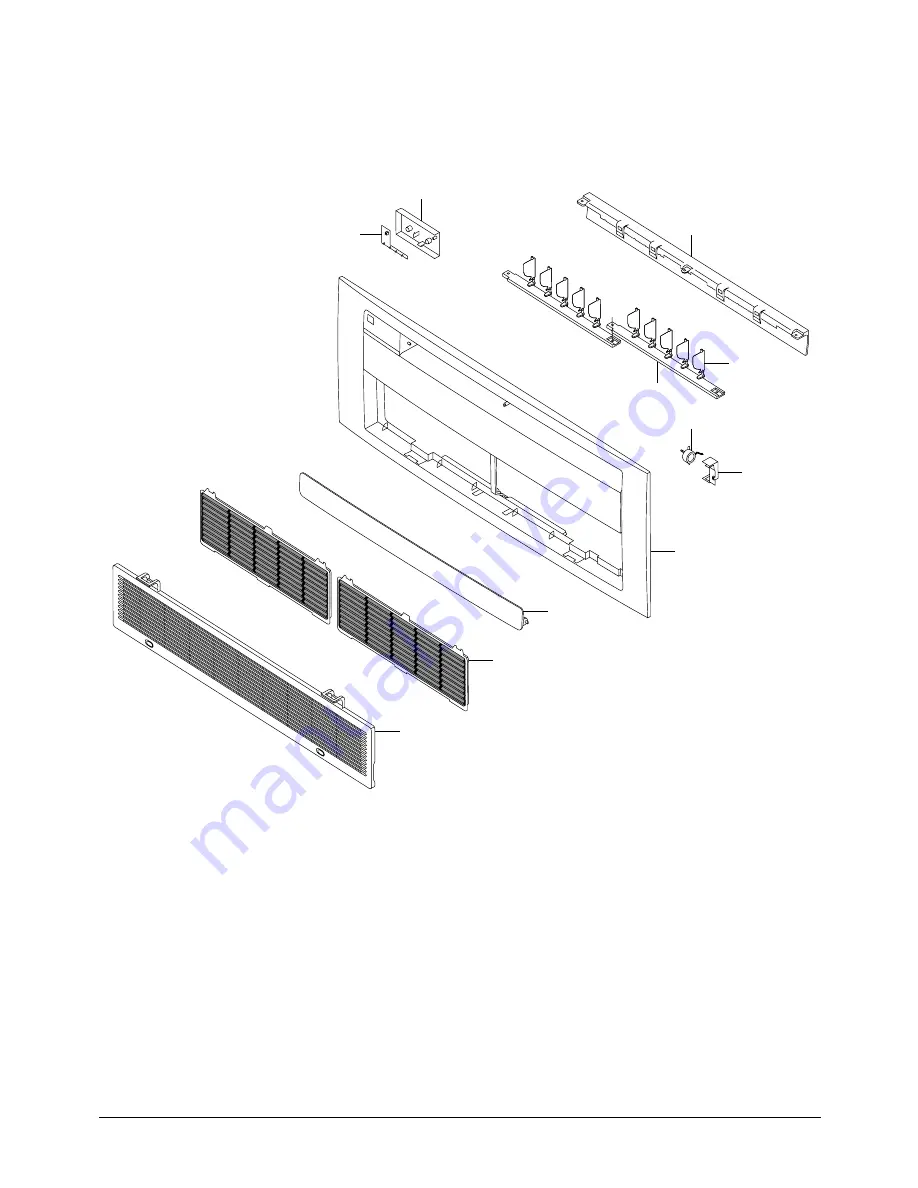
Exploded Views and Parts List
1
2
8
9
10
11
3
6
7
4
5
■
PK118MG
DB98-20241A(2)_2 05/1/25 5:07 AM Page 78
Page 1: ... MH18VP2X MH19VP2X MH052FXEA2 MH068FXEA4 MH080FXEA4 SERVICE Manual CONTENTS AIR CONDITIONER 1 Product Specifications 2 Operating Instructions 3 Disassembly and Reassembly 4 Refrigerating Cycle Diagram 5 Set Up the Model Option 6 Troubleshooting 7 Exploded Views and Parts List 8 Block Diagram 9 Wiring Diagram FREEJOINTMULTIAIRCONDITIONER ...
Page 2: ...7 ø9 52 x 7 ø18 x 2 000 Cross fan steel 11 2ROW 10STEP EEV Wall mounted 2 60 2 90 1 4 7 0 7 8 40 40 3 04 2 40 1 220 240 50 830 1 230 3 9 5 6 795 x 258 x 179 31 3 x 10 2 x 7 0 7 5 ø6 35 x 7 ø9 52 x 7 ø18 x 2 000 Cross fan steel 11 2ROW 10STEP EEV Type Cooling kW Heating Dehumidifying h Air Volume Cooling m3 min Heating Noise Cooling dB Heating Energy Efficiency Ratio Cooling Heating W W Power ø V H...
Page 3: ...240 50 1 550 2 250 7 0 10 1 1 080 x 315 x 205 42 5 x 12 4 x 8 1 13 ø6 35 x 7 ø12 7 x 7 ø18 x 2 000 Cross fan steel 19 2ROW 16STEP EEV Type Cooling kW Heating Dehumidifying h Air Volume Cooling m3 min Heating Noise Cooling dB Heating Energy Efficiency Ratio Cooling Heating W W Power ø V Hz Power Consumption Cooling W Heating Operating Current Cooling A Heating Outer Dimension W x H x D mm inch Weig...
Page 4: ... x 7 ø9 52 x 7 ø20 x 2 000 Cross fan steel 28 2ROW 14STEP EEV Duct 5 20 5 60 15 0 15 5 43 43 1 220 240 50 1 550 2 250 7 0 10 1 1 340 x 260 x 600 52 8 x 10 2 x 23 6 41 ø6 35 x 7 ø12 7 x 7 ø21 x 2 000 Sirocco steel 97 2ROW 12STEP EEV Type Cooling kW Heating Air Volume Cooling m3 min Heating Noise Cooling dB Heating Power ø V Hz Power Consumption Cooling W Heating Operating Current Cooling A Heating ...
Page 5: ...EH 600 OLP Propeller ø460 128 3 0 x 450 2ROW 28STEP EEV 1 700 2 0 6 5 2 2 7 3 48 56 57 770 2 240 850 2 420 3 6 9 9 3 9 10 7 20 880 x 368 x 310 600 OLP Propeller ø460 128 3 0 x 450 2ROW 28STEP EEV 1 700 Type Capacity Cooling kW Heating Air Volume m3 min Noise Cooling dB Heating Power ø V Hz Power Consumption Cooling W Heating Operating Current Cooling A Heating Fuse Capacity A Dimension W x H x D m...
Page 6: ... 9 48 58 59 830 2 505 1 230 2 705 3 9 10 9 5 6 11 9 30 880 x 796 x 330 72 Twin Rotary G5T360FU1EK 1 100 OLP Propeller ø460 128 3 0 x 450 2ROW 36STEP EEV 2 900 1 220 240V 50Hz Type Capacity Cooling kW Heating Air Volume m3 min Noise Cooling dB Heating Power ø V Hz Power Consumption Cooling W Heating Operating Current Cooling A Heating Fuse Capacity A Dimension W x H x D mm Weight kg Type Model Name...
Page 7: ... 2 8 2 58 7 8 2 21 27 21 9 10 1 57 5 13 9 21 7 9 4 57 1 11 4 32 22 4 11 3 56 0 16 4 22 2 10 6 55 8 14 5 21 30 3 9 4 78 5 12 8 30 2 9 0 78 5 10 2 35 27 30 9 10 6 78 7 16 8 30 7 10 0 78 0 14 2 32 31 6 12 0 76 3 19 4 31 7 11 4 76 7 17 2 21 36 1 9 8 89 8 12 8 36 2 9 4 91 5 11 4 43 27 37 0 11 1 90 5 17 7 36 8 10 6 89 1 14 2 32 37 6 12 5 88 2 20 6 37 4 11 8 86 8 16 7 170 ex 026 026 035 052 100 ex 026 02...
Page 8: ... 0 7 8 21 15 27 19 20 7 9 7 20 5 9 0 32 23 21 2 10 9 21 0 10 2 21 15 29 1 9 0 29 0 8 6 35 24 27 19 29 7 10 2 29 5 9 6 32 23 30 4 11 6 30 5 11 0 21 15 34 9 9 4 35 0 9 0 43 26 27 19 35 8 10 7 35 6 10 2 32 23 36 4 12 1 36 2 11 4 170 ex 026 026 035 052 100 ex 026 026 052 2 1 1 MH18AP1 P2 Cooling 17 5m Piping ...
Page 9: ...low T_dis T_suc 10 20 18 0 6 4 60 1 18 9 18 8 6 7 59 8 17 4 27 20 8 7 0 66 3 17 1 21 7 7 1 67 0 15 7 7 20 21 2 10 6 57 9 1 8 23 2 10 6 64 9 0 2 27 24 4 11 0 63 0 0 9 26 3 11 0 69 1 0 5 24 20 22 5 12 9 60 8 16 4 26 4 13 4 71 9 17 3 27 25 5 13 8 64 3 16 8 29 5 14 2 75 9 17 7 170 ex 026 026 035 052 100 ex 026 026 052 ...
Page 10: ...5m Piping Outdoor Indoor P_high P_low P_high P_low 10 20 15 16 8 6 0 17 6 6 3 27 15 19 6 6 6 20 5 6 7 7 6 20 15 20 0 10 2 22 0 10 2 27 15 23 2 10 6 25 1 10 6 24 18 20 15 21 3 12 5 25 2 13 0 27 15 24 3 13 4 28 3 13 8 170 ex 026 026 035 052 100 ex 026 026 052 ...
Page 11: ...7 8 2 21 27 21 9 10 1 57 5 13 9 21 7 9 4 57 1 11 4 32 22 4 11 3 56 0 16 4 22 2 10 6 55 8 14 5 21 30 3 9 4 78 5 12 8 30 2 9 0 78 5 10 2 35 27 30 9 10 6 78 7 16 8 30 7 10 0 78 0 14 2 32 31 6 12 0 76 3 19 4 31 7 11 4 76 7 17 2 21 36 1 9 8 89 8 12 8 36 2 9 4 91 5 11 4 43 27 37 0 11 1 90 5 17 7 36 8 10 6 89 1 14 2 32 37 6 12 5 88 2 20 6 37 4 11 8 86 8 16 7 170 ex 026 026 035 052 100 ex 026 026 052 ...
Page 12: ... 0 7 8 21 15 27 19 20 7 9 7 20 5 9 0 32 23 21 2 10 9 21 0 10 2 21 15 29 1 9 0 29 0 8 6 35 24 27 19 29 7 10 2 29 5 9 6 32 23 30 4 11 6 30 5 11 0 21 15 34 9 9 4 35 0 9 0 43 26 27 19 35 8 10 7 35 6 10 2 32 23 36 4 12 1 36 2 11 4 170 ex 026 026 035 052 100 ex 026 026 052 2 1 1 MH18AP1 P2 Cooling 17 5m Piping ...
Page 13: ..._low T_dis T_suc 10 20 18 0 6 4 60 1 18 9 18 8 6 7 59 8 17 4 27 20 8 7 0 66 3 17 1 21 7 7 1 67 0 15 7 7 20 21 2 10 6 57 9 1 8 23 2 10 6 64 9 0 2 27 24 4 11 0 63 0 0 9 26 3 11 0 69 1 0 5 24 20 22 5 12 9 60 8 16 4 26 4 13 4 71 9 17 3 27 25 5 13 8 64 3 16 8 29 5 14 2 75 9 17 7 170 ex 026 026 035 052 100 ex 026 026 052 ...
Page 14: ... 5m Piping Outdoor Indoor P_high P_low P_high P_low 10 20 15 16 8 6 0 17 6 6 3 27 15 19 6 6 6 20 5 6 7 7 6 20 15 20 0 10 2 22 0 10 2 27 15 23 2 10 6 25 1 10 6 24 18 20 15 21 3 12 5 25 2 13 0 27 15 24 3 13 4 28 3 13 8 170 ex 026 026 035 052 100 ex 026 026 052 ...
Page 15: ... the pressing the temp button On Timer button The On Timer enables you to switch on the air conditioner automatically after a given period of time that is from 30 minutes to 24 hours To cancel press the Set Cancel button Off Timer button The Off Timer enables you to switch off the air conditioner automatically after a given period of time that is from 30 minutes to 24 hours To cancel press the Set...
Page 16: ... is increased by the pressing the temperature button On Off UP DOWN Low Medium High Automatic rotated Sleep button The sleep timer can be used when you are cooling or heating your room to switch the air conditioner off automatically after a period of 6 hours Turbo button The air conditioner cools or heats the room as quickly as possible After 30 minutes the air conditioner is reset automatically t...
Page 17: ... more times until the required time display FUNCTION BUTTON No 8 9 10 11 On Timer button The On Timer enables you to switch on the air conditioner automatically after a given period of time that is from 30 minutes to 24 hours To set the operating time press the button one or more times until the required time display Timer Set Cancel button After setting On Timer or Off Timer press the button to s...
Page 18: ...on Low temperature release Prevention against freeze 5 TURBO MODE This mode is available in AUTO COOL HEAT DRY FAN MODE When this button is pressed at first the air conditioner is operated powerful state for 30 minutes regardless of the set temperature room temperature When this button is pressed again or when the operating time is 30 minutes turbo operation mode is canceled and returned to the pr...
Page 19: ...MER The On Timer enables you to switch on the air conditioner automatically after a given period of time You can set the period of time from 30 minutes to 24 hours OFF TIMER The Off Timer enables you to switch off the air conditioner automatically after a given period of time You can set the period of time from 30 minutes to 24 hours 11 BUZZER SOUND Whenever the On Off button is pressed or wheneve...
Page 20: ...nt Grille down then disassemble it by pulling it forwards 4 Open the upper Front Grille by pulling right and left sides of the Grille 5 Take the left and right Filter out 6 Loosen one of the right screw and detach the Terminal Cover 7 Detach the thermistor from the Front Grille 8 Loosen 5 fixing screws of Front Grille 9 Pull the lower left and right of discharge softly for the outside cover to be ...
Page 21: ... Panel Grille with the thumb to remove the hook And press the right of the upper side of the Panel Grille with the fingers And then disassemble the Panel Grille 1 Take all the connector of PCB upper side out Including Power Cord 2 Detach the outdoor unit connection wire from the Terminal Block 3 If pulling the main PCB up it will be taken out 1 Pull Tray Drain out from the Back Body ...
Page 22: ...e 2 Detach the Connection Pipe 3 Detach the Holder Pipe at the rear side 4 Loosen 3 fixing screws of right and left side 5 Detach the Heat Exchanger from the indoor unit 1 Loosen 2 fixing screws and detach the Motor Holder 2 Loosen the fixing screw of Fan Motor with a M3 wrench 3 Detach the Fan Motor from the Fan 4 Detach the Fan from the left Holder Bearing ...
Page 23: ...eft sides of the Grille 5 Take the left and right Filter out 6 Loosen one of the right screw and detach the Terminal Cover 7 Detach the thermistor from the Front Grille 8 Loosen 5 fixing screws of Front Grille 9 Pull the lower left and right of discharge softly for the outside cover to be pulled out 10 In order to disassemble the Panel Grille press in order the left center and right of the upper s...
Page 24: ...uding Power Cord 2 Detach the outdoor unit connection wire from the Terminal Block 3 If pulling the main PCB up it will be taken out 1 Pull Tray Drain out from the Back Body 1 Loosen 2 fixing earth screws of right side 2 Detach the Connection Pipe 3 Detach the Holder Pipe at the rear side 4 Loosen 3 fixing screws of right and left side 5 Detach the Heat Exchanger from the indoor unit ...
Page 25: ...ics 24 No Parts Procedure Remark 5 Fan Motor Cross Fan 1 Loosen 2 fixing screws and detach the Motor Holder 2 Loosen the fixing screw of Fan Motor with a M3 wrench 3 Detach the Fan Motor from the Fan 4 Detach the Fan from the left Holder Bearing ...
Page 26: ...MPORTANT You must give attention when disassembling the Front Grille and must check the safety clips have been installed If you don t ensure them the Front Grille will drop suddenly and you will be hurt 2 Detach the Front Grille 1 Remove the safety clips 2 Open the Front Grille about 45 and pull it forward 3 Pull out the Air Filter 3 1 3 MH026FKEA MH035FKEA ...
Page 27: ... Reassembly Samsung Electronics 26 No Parts Procedure Remark 2 Front Panel 1 Loosen 6 fixing screws holding the panel as shown picture 2 Detach the Front Panel pressing the 2 hooks on the both sides of the indoor unit ...
Page 28: ...sembly and Reassembly 27 Samsung Electronics No Parts Procedure Remark 3 Drain Panel 1 Loosen 4 fixing screws for Ass y Drain Panel around as shown in pictures 2 Detach Ass y Drain Panel as shown in Pictures ...
Page 29: ...sembly Samsung Electronics 28 No Parts Procedure Remark 4 Control In 1 Detach the Control Cover after disassembling 2 screws as shown in pictures 2 Detach the wire connection part of the Ass y Main PCB as shown in picture ...
Page 30: ...sembly and Reassembly 29 Samsung Electronics No Parts Procedure Remark 3 Loosen 2 fixing screws of Case Control as shown in pictures 4 Loosen the fixing screw 5 Detach the Ass y Case Control part pulling up ...
Page 31: ...embly Samsung Electronics 30 No Parts Procedure Remark 6 Loosen the fixing screw and detach earth cable 7 Loosen the fixing screw and detach Terminal Cover as shown in pictures 8 Loosen 2 fixing screws as shown in pictures ...
Page 32: ...assembly and Reassembly 31 Samsung Electronics No Parts Procedure Remark 9 Loosen 2 fixing indicating screws of earth cable and the fixing screw of Base Terminal 10 Detach Base Terminal as shown in picture ...
Page 33: ...No Parts Procedure Remark 5 6 Drain Panel Sub Evap 1 Detach Ass y Drain Panel Sub after loosen 2 fixing screws both side of it 1 Loosen 4 fixing screws of Ass y Evap around 2 Loosen 2 fixing screws as shown in picture and detach Ass y Cabinet Side LF B ...
Page 34: ... 3 Detach Ass y Evap pulling up from the indoor unit as shown in picture 1 Loosen 3 fixing screws of cover Fan Motor and detach cover Fan Motor 2 Detach Ass y Cross Fan as shown in picture 1 Loosen 4 fixing screws as shown in picture 2 Detach Drain Hose and detach Ass y Drain Pump as shown in pictures ...
Page 35: ...ction of 2 Plate Handle places by use of screw as shown in 2 2 Turn the Plate Handle by hand when removing the Filter Pre 3 When pulling the Filter Pre handle the Filter Pre can be assembled Be sure to remove the cushion on the marked part after initial installation It cause the damage of noise 1 After disassembling 9 fixing screws detach Ass y Cover Bottom 3 1 4 MH052FDEA ...
Page 36: ...Parts Procedure Remark 2 Loosen 6 fixing screws 3 Detach the Sensor Holder from the Ass y Fan Case 4 Detach from Ass y Control In the capacitor connection wire between the Motor Fan in and housing Connector 5 Detach the Ass y Blower and Duct from the set ...
Page 37: ...rk 3 Control In 1 Loosen the fixing screw detach the Cover Control 2 Detach the Motor Fan in and Sensor Connector connected to PCB 3 Loosen 2 fixing screws mark 4 Hold the Ass y Control In by hand to lift up a little and then release the status of hanging on the hanging slot ...
Page 38: ...ng screws to detach Ass y Drain Pan 2 screws each at left and right side Work is possible when disassembling the Ass y Drain Pan 1 Loosen 8 fixing screws 4 each at left and right side 2 Loosen 6 fixing screws 3 Loosen 5 fixing screws It is possible at the status of No 3 Ass y Control In disassembly at the time ...
Page 39: ...msung Electronics 38 No Parts Procedure Remark 4 Loosen 4 fixing screws 5 Pull the Cabinet Side LF RH by hand to disassemble 6 Loosen 4 fixing screws 2 each at left and right side 7 Detach it from the set if the Ass y Evap pull up ...
Page 40: ...let When connecting canvas to the discharge side 1 Loosen 4 fixing screws 2 each at left and right side 2 Loosen 12 fixing screws 6 each at upper and lower side After connecting canvas to the disassembled Ass y Holder Outlet 2 attach the Ass y Holder Outlet to the set in the reverse order ...
Page 41: ...nal Block 3 Loosen 8 fixing screws and detach the Cabinet Upper 4 Loosen 2 fixing screws 7 bolts and detach the Front Cabinet 5 Loosen 2 fixing screws and pull up the Control Box 3 2 1 MH052FXEA2 MH18VP2X MH19VP2X 3 2 Outdoor Unit Take care of the electrical shock by contact on the charging parts before the discharge after power off If takes approximately 2 minutes to discharge ...
Page 42: ...Remark 2 Fan Motor 6 Loosen 9 fixing screws and detach the Cabinet Side 7 Detach the Terminal and detach the Compressor Lead Wire 1 Loosen the fixing nut and detach the Fan 2 Loosen 4 fixing bolts and detach the Motor 3 Loosen 2 fixing bolts and detach the Bracket Motor ...
Page 43: ...ocedure Remark 3 Heat Exchanger Compressor 1 Release the refrigerant at first 2 Disassemble the Inlet and Outlet Pipe by welding 3 Loosen the fixing screws of the Heat Exchanger 4 Detach the Heat Exchanger 5 Loosen 3 nuts of the Compressor 6 Detach the Compressor ...
Page 44: ...Loosen the fixing screw and detach the Cover Control 2 Detach the Cable Connector Wire from the Terminal Block 3 Loosen 8 fixing screws and detach the Cabinet Upper 4 Loosen 6 fixing screws 7 bolts and detach the Cabinet Front 5 Loosen 4 fixing screw and pull up the Control Box 3 2 2 MH068FXEA4 MH080FXEA4 ...
Page 45: ...Remark 2 Fan Motor 6 Loosen 12 fixing screws and detach the Cabinet Side 7 Detach the Terminal Cover and detach the comp lead wire 1 Loosen the fixing nut and detach the Fan 2 Loosen 4 fixing bolts and detach the Motor 3 Loosen 3 fixing bolts and detach the Bracket Motor ...
Page 46: ...ocedure Remark 3 Heat Exchanger Compressor 1 Release the refrigerant at first 2 Disassemble the Inlet and Outlet Pipe by welding 3 Loosen the fixing screw of the Heat Exchanger 4 Detach the Heat Exchanger 5 Loosen 3 nuts of the Compressor 6 Detach the Compressor ...
Page 47: ...A MH18VP2 09 MH18VP2 09 4 Refrigerating Cycle Diagram 4 1 MH052FXEA MH18VP2X 1 4 1 2 Header 5 8 Distributor 3 8 3 8 Service v v 1 2 Service v v 1 4 Receiver 1 4 1 4 EEV OUTDOOR UNIT INDOOR UNIT ROOM A ROOM B Inverter Comp Main accum Sub accum 1 2 1 2 2 1 ...
Page 48: ...ex 2 Rooms MH19VP2X 07 MH19VP2X 12 4 2 MH19PV2X 1 4 1 2 Header 5 8 Distributor 3 8 3 8 Service v v 1 2 Service v v 1 4 Receiver 1 4 1 4 EEV OUTDOOR UNIT INDOOR UNIT ROOM A ROOM B Inverter Comp Main accum Sub accum 1 2 1 2 2 1 ...
Page 49: ...H035FPEA MH052FPEA 4 3 MH068FXEA4 MH080FXEA4 Inverter Comp Main accum Sub accum 1 2 3 8 1 2 Service v v 5 8 Header 5 8 Distributor 3 8 3 8 3 8 1 2 Service v v 3 8 Receiver 1 2 1 4 1 4 1 4 1 4 EEV 1 2 3 4 OUTDOOR UNIT INDOOR UNIT ROOM A ROOM B ROOM C ROOM D ...
Page 50: ...or repeatedly Setting is not required if you must a value which has a default Push the button to set the display panel to Every time you push the button the display panel reads repeatedly 3 Push the button to set the display panel to Every time you push the button the display panel reads repeatedly 4 Push the button to set the display panel to Every time you push the button the display panel reads...
Page 51: ... key with the direction of remote control for set 7 8 Press button then the default value is Push the button to set the display panel to Every time you push the button the display panel reads repeatedly 10 Push the button to set the display panel to Every time you push the button the display panel reads repeatedly 9 Push the button to set the display panel to Every time you push the button the dis...
Page 52: ... the button the display panel reads or repeatedly Push the button to set the display panel to Every time you push the button the display panel reads repeatedly Setting is not required if you must a value which has a default 3 Push the button to set the display panel to Every time you push the button the display panel reads repeatedly 4 Push the button to set the display panel to Every time you pus...
Page 53: ...ction key to set the display part to and check the display part The display part shows Press the Mode Selection key to set the display part to and check the display part The display part shows Step 4 Pressing the ON OFF button When pressing the operation ON OFF key with the direction of remote control for unit the sound Ding or Diriring is heard and the OPERATION ICON lamp of the display is flicke...
Page 54: ...ble of the option code MODEL OPTION CODE MH020FPEA MH19VP2 07 0d7400 13223F MH023FPEA MH026FPEA MH18VP2 09 0d6400 142351 MH035FPEA MH19VP2 12 0d7404 162362 MH052FPEA 0d5408 192351 MH026FKEA 005600 14221d MH035FKEA 005600 162340 MH052FDEA 015200 190000 ...
Page 55: ...the air conditioner does not operate The compressor and indoor fan stop intermittently in HEAT mode Indoor fan and outdoor fan stop operation intermittently in a HEAT mode The compressor stops intermittently in a COOL mode or DRY mode and fan speed of the indoor unit decreases Explanation In happens after a delay of 3 minutes when the compressor is reoperated The same phenomenon occurs when a powe...
Page 56: ... 2 K4 View mode Display changes 6 2 Checking and Testing operations K 1 1 2 3 4 K 2 K 3 K 4 Number of indoor unit AUTO Addressing MANUAL Addressing 7 segment LED 2digits x 2 Push Key K1 K2 K3 K4 1 Heat mode Try run Display Reset View mode change 2 3 4 Refrigerant Charging Display Cool mode Try run Display Pump down Display Checking of pipe connection Display K 1 K 2 K 3 OFF DIS01 SW02 SW01 K 4 DIS...
Page 57: ...l controls which indoor unit 2 It takes 5 to 50 minute to complete This time depends on the outdoor temperature and number of indoor unit 2 During this mode LED on the right 2 digit shows EEV number and the indoor address which is checking at the time see right figure 2 If checking finished with no error LED display returns to normal display 2 If finished with error right digit will show the EEV n...
Page 58: ... E185 is displayed on indoor unit LED check communi cation wire and power wire connection 4 If error code E460 is displayed on outdoor unit LED AC power line could be connected to outdoor communication terminal F1 F2 So check the wiring not only communication line but also power line 5 If error code E401 E404 or E416 is displayed on outdoor unit LED check PIPE connection also Because gas flow to a...
Page 59: ... unit PCB Outdoor temperature sensor error Short Open Temperature sensor Error level over 4 9V 50 C under 0 4V 93 C Condenser temperature sensor error Short Open Temperature sensor Error level over 4 9V 50 C under 0 4V 93 C Condenser temperature sensor detached Temperature sensor Compressor discharge sensor error Short Open Error check condition outdoor temperature over 20 C Temperature sensor Err...
Page 60: ...LP temperature limit control Outdoor fan Compressor Outdoor controller Outdoor fan Compressor Compressor peak current protection Compressor wire Outdoor controller Outdoor fan EEV Compressor overload protection by current Service valve Outdoor controller DC link voltage error under 150V or over 410V Power voltage This error might display for a few seconds after power cut Outdoor controller Compres...
Page 61: ...tached Heat exchanger in sensor Indoor unit heat exchanger out temperature sensor detached Heat exchanger out sensor Indoor unit heat exchanger in out temperature sensor detached Heat exchanger in out sensor Indoor unit fan motor malfunction Fan motor and cable More than 2 indoor units cool and heat simultaneously Another indoor unit operation mode EEPROM error Indoor PCB Option code setting error...
Page 62: ... of COND sensor Error of DISCHARGE sensor 1 No communication for 2 minutes between indoor unit and outdoor unit communication error for more than 2 minutes 2 Indoor unit receiving the communication error from outdoor unit 3 Outdoor unit tracking 3 minutes error 4 When sending the communication error from outdoor unit due to the mismatching of the communication numbers and installed numbers after c...
Page 63: ...mperature sensor in indoor unit OPEN SHORT Error of heat exchanger sensor in indoor unit Error of heat exchanger OUT sensor in indoor unit Error of outlet temperature sensor in indoor unit OPEN SHORT For heat pump models only Error of mixed operation Error of outdoor temperature sensor Error of COND sensor Error of DISCHARGE sensor 1 No communication for 2 minutes between indoor unit and outdoor u...
Page 64: ...nditions 5 Breakaway of COND MID sensor 6 2nd detection of refrigerant completely leak 7 2nd detection of high temperature COND 8 2nd detection of high temperature DISCHARGE 9 COMP DOWN due to 2nd detection of low pressure switch 10 Error of reverse phase 11 Compressor down due to 6th detection of freezing 12 Self diagnosis of condensation sensor G8 G9 13 Compressor down due to condensation ratio ...
Page 65: ...nal receiving path front panel dirt infrared receiving module wiring Check operation ON OFF by the button at By buzzer sound and Indoor unit lower right of the display module LED display Wiring cable to outdoor unit Any Error code on LED display Error code starts in Consult error code table Wait for 5 minutes to check error code Error code consists of 4 because some error judgement needs digits an...
Page 66: ... detects some hardware trouble or abnormal condition Troubleshooting Yellow Green Red Description Note Status indication OFF OFF OFF Power OFF No power SMPS error ON ON ON Power on reset 1 2 seconds If always in this pattern IC01 inverter micom has some trouble OFF Blink ON Normal operation Hardware trouble OFF OFF ON Communication Error between Main micom and inverter micom Blink Blink ON Current...
Page 67: ...in case of 3 0A above DC link voltage will go up over 300V This voltage is in proportion to AC input voltage Current can be monitored with VIEW MODE Press K4 key on the outdoor display PCB for several times to change the display to sensor temperature value Left 1 digit of the LED is data index and Right 3 digits are the value Item Measuring point Normal value DC LINK Q803 E D101 Cathode about 1 4 ...
Page 68: ... PCB 1 1 Normal voltage is between 11 5V and 12 5V 1 1 DC voltage is supplied from CN90 on the inner AC PCB Pin layout is as follows 1 1 Pin 7 GND Pin 8 5V Pin 9 12V 6 3 4 Checking Power cable and Communication cable See 6 2 Checking and Testing operations and installation manual 6 3 5 Checking Temperature sensor See 6 5 Fault Diagnosis of Major Parts In case of a sensor in outdoor unit temperatur...
Page 69: ... PCB for several time to change the display to current EEV value Left 1 digit of the LED is data index and Right 3 digits is the value 6 3 7 Pipe matching See 6 2 Checking and Testing operations 6 3 8 Checking Motor in indoor unit See 6 5 Fault Diagnosis of Major Parts Index Value Remark 3 EEV A step 4 EEV B step The step value range is between 5 EEV C step zero and 480 6 EEV D step ...
Page 70: ...e to polish them using an emery paper or the like before soldering them Since the lead wires of any new part are covered with an oxide film solder cannot adhere to the lead wires if not polished 6 When soldering any part care should be exercised not to apply any high wattage soldering iron to the part for a long time Some parts are of so low a heat resistance that they may be broken or have the pr...
Page 71: ...ormal At the normal temperature 10 C 30 C Abnormal 0Ω open or short Measure the resistance between terminals of the Motor connector housing Normal Abnormal 0Ω open or short Measure the resistance between terminals of the Motor connector housing Normal 40 50Ω Orange Gray Red Gray Yellow Gray Black Gray Abnormal 0Ω open or short Measure the resistance between terminals Normal 1 1 1 3KΩ Abnormal 0Ω o...
Page 72: ...MEMO 71 Samsung Electronics ...
Page 73: ... 6 15 1 4 1 3 1 2 1 1 1 1 1 3 3 1 3 2 7 10 7 2 7 3 7 1 8 9 13 14 12 You can search for the updated part code number through the ITSELF URL http itself sec samsung co kr 7 Exploded Views and Parts List 7 1 Indoor Unit 7 1 1 MH020FPEA MH023FPEA MH026FPEA MH035FPEA MH18VP2 09 MH19VP2 07 MH19VP2 12 ...
Page 74: ...67E ASS Y FILTER BIO ASS Y 1 5 DB63 00581A COVER TERMINAL HIPS DB63 00588A COVER TERMINAL HIPS 1 6 DB93 02531P ASS Y REMOCON ASS Y 1 7 DB94 00488A ASS Y BACK BODY SUB ASS Y DB94 00486A ASS Y BACK BODY SUB ASS Y 1 7 1 DB61 01098A BACK BODY HIPS DB61 01119A BACK BODY HIPS 1 7 2 DB63 00580A COVER IONIZER HIPS 1 7 3 DB94 00258A ASS Y BEARING ASS Y 1 8 DB94 00040R ASS Y CROSS FAN ASS Y DB94 00040F ASS ...
Page 75: ...ung Electronics 74 Exploded Views and Parts List 7 1 2 MH052FPEA 4 6 12 4 12 2 12 1 12 5 12 3 12 6 2 8 5 1 1 1 2 1 1 3 1 1 4 1 1 5 1 1 6 12 1 4 1 3 1 1 1 1 1 3 7 7 5 7 6 7 7 7 4 7 1 7 3 7 2 10 7 8 1 2 11 9 ...
Page 76: ...S Y 5 DB63 00594A COVER TERMINAL HIPS 6 DB93 02531P ASS Y REMOCON ASS Y 7 DB94 00531A ASS Y BACK BODY ASS Y 7 1 DB94 00040J ASS Y CROSS FAN ASS Y 7 2 DB60 20011A BOLT SPECIAL M6 7 3 DB31 10151C MOTOR FAN IN 7 4 DB61 01135A BACK BODY HIPS 7 5 DB61 01136A HOLDER MOTOR PP 7 6 DB63 00580A COVER IONIZER HIPS 7 7 DB73 00128A RUBBER BEARING 7 8 DB94 40007A ASS Y BEARING MOTOR 8 DB67 60030A SPRING SENSOR ...
Page 77: ...Samsung Electronics 76 Exploded Views and Parts List 7 1 3 MH026FKEA MH035FKEA 13 12 11 10 9 3 1 8 7 6 18 3 1 22 23 2 4 5 15 16 19 20 21 14 1 17 24 14 2 14 ...
Page 78: ...VER FAN MOTOR Fire Resistant P S V0 1 1 11 DB61 00362A CASE CONTROL Fire Resistant P S V0 1 1 12 DB93 02335D ASS Y PCB ASS Y 1 1 13 DB63 00167A COVER CONTROL ASS Y 1 1 14 DB96 01190H ASS Y EVAP IN ASS Y 1 1 14 1 DB60 00057A SPACER EVAP ABS 1 1 14 2 DB32 00035B THERMISTOR ASS Y 103AT 1 1 15 DB61 00365A BRACKET TERMINAL SGCC M 1 1 16 DB61 00394A BASE TERMINAL ABS 1 1 17 DB65 00004B TERMINAL BLOCK DA...
Page 79: ...Samsung Electronics 78 Exploded Views and Parts List 1 2 8 9 10 11 3 6 7 4 5 PK118MG ...
Page 80: ...ADE V HIPS UL94 V0 10 3 DB66 00157A LINK BLADE LF POM 2 4 DB63 00163A COVER PCB CASE HIPS UL94 V0 1 5 DB93 01021A ASS Y PCB DISPLAY 1 6 DB31 10153D MOTOR STEP MSFCC20A05 1 7 DB61 00535A HOLDER MOTOR HIPS UL94 V0 1 8 DB64 00234B PANEL FRONT HIPS UL94 V0 1 9 DB66 00159A BLADE H HIPS UL94 V0 1 10 DB64 00243B GRILLE FRONT HIPS UL94 V0 1 11 DB64 00244A GRILLE INLET AIR PP 1 ...
Page 81: ...Samsung Electronics 80 Exploded Views and Parts List 7 1 4 MH052FDEA 1 2 5 13 18 10 11 19 17 9 4 14 15 7 8 6 16 3 12 19 2 19 6 19 3 19 1 5 1 5 6 5 5 5 4 5 2 5 7 5 3 19 4 19 5 ...
Page 82: ...R FAN IN BRACKET MOTOR GUIDE ASS Y CABI LF ASS Y CABI INLET LF PLATE HANGER LF ASS Y EVAP UNIT ASS Y CABI INLET RH ASS Y CABI SIDE RH PLATE HANGER RH CABINET SIDE RH B ASS Y HOLDER OUTLET ASS Y COVER BOTTOM PLATE HANDLE FILTER PRE COVER CONTROL ASS Y CONTROL IN ASS Y CASE CONTROL ASS Y PCB MAIN TERMINAL BLOCK 6P TERMINAL BLOCK 6P C FILM TRANS POWER HOLDER WIRE SGCC M T0 8 SGCC M T0 8 ASS Y BLK SGC...
Page 83: ...Samsung Electronics 82 8 17 7 13 16 16 1 17 1 16 2 13 1 2 14 15 9 10 1 1 1 3 4 18 5 6 11 12 7 2 Outdoor Unit MH052FXEA2 MH18VP2X MH19VP2X ...
Page 84: ...1907A ASS Y CABINET SIDE 1 1 1 10 DB90 40176B ASS Y COVER CONTROL 1 1 1 11 DB90 10616N ASS Y CABINET UPPER 1 1 1 12 DB63 00343A GUARD COND 1 1 1 13 G4B135LU1EH ROTARY COMPRESSOR 1 1 1 13 1 DB73 00070A GROMMET ISOLATOR 3 3 3 14 DB96 04469A ASS Y TUBE SUCTION 1 1 1 15 DB99 00607A ASS Y 4 WAY VALVE 1 1 1 16 DB99 00608A ASS Y VALVE 1 1 1 16 1 DB96 04450A ASS Y TUBE EEV A 1 1 1 16 2 DB96 04451A ASS Y T...
Page 85: ...Samsung Electronics 84 Exploded Views and Parts List 11 3 1 9 1 1 10 2 14 13 1 21 15 16 6 18 7 4 5 12 17 17 1 13 16 1 16 2 16 3 16 4 20 19 8 MH068FXEA4 MH080FXEA4 ...
Page 86: ...11 DB90 01007B ASS Y COVER TOP 1 1 12 DB63 01058A GUARD COND 1 1 13 G5T360FU1EK ROTARY COMPRESSOR 1 1 13 1 DB73 00082A GROMMET ISOLATOR 3 3 14 DB96 03803A ASS Y TUBE SUCTION 1 1 15 DB96 03788A ASS Y 4 WAY VALVE 1 1 16 DB99 00557A ASS Y VALVE 1 1 16 1 DB96 03789A ASS Y TUBE EEV A 1 1 16 2 DB96 03790A ASS Y TUBE EEV B 1 1 16 3 DB96 03791A ASS Y TUBE EEV C 1 1 16 4 DB96 03792A ASS Y TUBE EEV D 1 1 17...
Page 87: ...y Control In Indoor Unit Material LDPE Adhesive protected vinyl SPEC T0 03 Square 75x75 Be sure to cover the side of cylinder of ejected material BAR CODE ATTACHIMENT Detecting side MH020FPEA MH023FPEA MH026FPEA MH18VP2 09 MH19VP2 07 ...
Page 88: ...HERMISTOR ASS Y 1 10 6001 000929 SCREW MACHINE PH M3xL22 1 11 6001 000572 SCREW MACHINE TH M4xL10 1 12 6001 000725 SCREW MACHINE TH M4xL16 2 13 DB93 01380B C W MODULE ASS Y 1 14 DB39 00643M C W STEP MOTOR UP DOWN ASS Y 1 15 DB62 01368X SEAL 61x40x3 30FOAM PE GRAY 1 16 6002 000538 SCREW TAPPING PH M4xL8 1 17 DB39 00780B C W STEPPING MOTOR ASS Y AUTO GRILLE 1 18 DB61 01110A HOLDER DISPLAY ABS 1 19 D...
Page 89: ...onics 88 Exploded Views and Parts List Material LDPE Adhesive protected vinyl SPEC T0 03 Square 75x75 Be sure to cover the side of cylinder of ejected material BAR CODE ATTACHIMENT Detecting side MH035FPEA MH19VP2 12 ...
Page 90: ...9 DB32 00093A ASS Y THERMISTOR ASS Y 1 10 6001 000929 SCREW MACHINE PH M3xL22 1 11 6001 000572 SCREW MACHINE TH M4xL10 1 12 6001 000725 SCREW MACHINE TH M4xL16 2 13 DB93 01380A C W MODULE ASS Y 1 14 DB39 00643F C W STEP MOTOR UP DOWN ASS Y 1 15 DB62 01368X SEAL 61x40x3 30FOAM PE GRAY 1 16 6002 000538 SCREW TAPPING PH M4xL8 1 17 DB39 00780B C W STEPPING MOTOR ASS Y AUTO GRILLE 1 18 DB61 01110A HOLD...
Page 91: ...Samsung Electronics 90 Material LDPE Adhesive protected vinyl SPEC T0 03 Square 100x100 Be sure to cover the side of Holder Display Exploded Views and Parts List MH052FPEA DB93 02744A ...
Page 92: ...3 DB93 01384B ASS Y C W AC DC CONNECTION ASS Y 1 14 DB93 01380C ASS Y C W MODULE PCB ASS Y 1 15 DB93 01543A C W STEP MOTOR UP DOWN ASS Y 1 16 2301 001371 CAPACITOR 2 0uF 450VAC 1 17 DB32 00020H ASS Y THERMISTOR 4P 103AT 1 18 DB62 01368X SEAL 61x40x3 30FOAM PE 1 19 DB61 01106A CASE CONTROL DC HIPS VO 1 20 6501 000123 CABLE TIE DA 140 1 21 DB32 00029G EVA OUT ASS Y 1 22 DB39 00780B ASS Y C W AUTO GR...
Page 93: ...Samsung Electronics 92 Exploded Views and Parts List MH026FKEA MH035FKEA DB90 00590A Bar code apply Insert into the lower part ...
Page 94: ... HOLDER WIRE ABS BLK 2 2 5 DB65 10088B CABLE TIE 1 1 6 6002 000234 SCREW TAPPING ZPC YEL 4 4 7 6001 000841 SCREW MACHINE ZPC YEL 2 2 8 6009 001001 SCREW SPECIAL ZPC YEL 2 2 9 6002 000231 SCREW TAPPING ZPC YEL 2 2 10 DB61 00365A BRACKET TERMINAL SGCC M 1 1 11 DB61 00163A BRACKET EARTH SGCC M 1 1 12 DB39 00255A C W POWER COMMUNICATION 1 1 13 DB39 00165A CONNECTOR WIRE EARTH 1 1 14 DB68 01975A LABEL ...
Page 95: ...3 01037Y A Part CAPACITOR CAPACITOR B Part Storing being assembled with blower part ASS Y Position for the attachment of label name Model No 3 Wire connection diagram DB65 00004L apply PowerCord Ventilatior Heater IndoorUnitCommunication Connectionofwiredremotecontrol ...
Page 96: ... WIRE HOT WATER HEATER 1 7 DB26 10065B TRANS POWER DC17V DC500mA 1 8 DB61 40291B HOLDER WIRE PP 2 9 2301 001369 C OIL 3 0uF 450VAC 1 10 DB61 00449A CASE PCB ABS 1 11 6002 000231 SCREW TAPPING TH 2S M4x12 ZPC YEL 4 12 6001 000044 SCREW MACHINE TH M4 L18 ZPC YEL 4 13 SCREW TAPPING PH M4 L22 2 14 DB73 30039A BUSHING NR BLK T7xD37 1 15 DB69 60008A BAND CAPACITOR SBHG1 M T0 8 1 16 DB73 30038B BUSH COND...
Page 97: ... 24 11 15 22 21 13 14 2 7 20 19 17 18 16 32 12 11 8 35 36 15 14 13 12 13 14 15 5 4 3 1 30 36 29 6 34 12 11 35 27 10 8 28 23 Connect to CN58 Connect to CN57 Connect to CN61 80 10 10 Cable Tie 7mm 200 7 4 Ass y Control Out Outdoor Unit MH052FXEA2 MH18VP2X MH19VP2X ...
Page 98: ...2 15 DB39 00765P CONNECT WIRE 1 16 DB93 02894A ASS Y PCB OUT DISPLAY 1 17 DB61 01948A CASE SUB PCB 1 18 DB65 40062S TERMINAL BLOCK 1 19 DB61 00586A HOLDER WIRE UP 1 20 DB61 00587A HOLDER WIRE DOWN 1 21 DB62 03330A HEAT SINK 1 22 DB81 00547A INSULATOR MICA T0 1 45x28 1 23 DB61 02254A CASE CONTROL BASE 1 24 2301 001369 FAN MOTOR CAPACITOR 3 0µF 450V 1 25 DB61 01198A CASE CONTROL UPP 1 26 DB62 01925B...
Page 99: ...ire The assembly shape of wire is omitted Refer to the drawing of right side for the assembly shape Connect to CN58 Connect to CN57 Connect to CN61 25 34 9 30 31 30 26 26 34 12 16 10 3 8 35 33 14 13 22 8 11 12 27 28 5 15 35 10 14 13 20 21 30 30 23 18 19 17 27 28 34 24 15 11 17 4 5 2 1 29 15 30 32 36 7 6 31 12 11 13 14 MH068FXEA4 MH080FXEA4 ...
Page 100: ...39 00765P CONNECT WIRE 1 16 DB93 02894A ASS Y PCB OUT DISPLAY 1 17 DB61 01948A CASE SUB PCB 1 18 DB65 40062S TERMINAL BLOCK 1 19 DB61 40291B HOLDER WIRE 3 20 DB62 02900A HEAT SINK 1 21 DB81 00547A INSULATOR MICA T0 1 45x28 1 22 DB62 03079A HEAT SINK PLATE 1 23 DB61 01197A CASE CONTROL BASE 1 24 2301 001369 FAN MOTOR CAPACITOR 3 0uF 450V 1 25 DB61 01198A CASE CONTROL UPP 1 26 DB62 01925B INSUL CONT...
Page 101: ...detect Address S W Buzzer SSR SMPS Indoor Unit control MICOM Comm Interface RS485 Comm Interface RS485 System control Micom Comm Interface RS485 Inverter Micom Relay EMI Filter Relay x2 Relay SMPS Inverter driver PFC driver Terminal block L N F1 F2 V1 V2 Indoor Unit 2 Indoor Unit 3 OUTDOOR UNIT Indoor Unit 4 Center controller Option Transmitter Option Wired remote controller Option Wireless remote...
Page 102: ...amsung Electronics 9 Wiring Diagram 9 1 Indoor Unit This Document can not be used without Samsung s authorization Code No DB98 20172A MH020FPEA MH023FPEA MH026FPEA MH035FPEA MH18VP2 09 MH19VP2 07 MH19VP2 12 ...
Page 103: ...Samsung Electronics 102 Wiring Diagram This Document can not be used without Samsung s authorization Code No DB98 20217A MH052FPEA ...
Page 104: ...103 Samsung Electronics Wiring Diagram This Document can not be used without Samsung s authorization MH026FKEA MH035FKEA Code No DB98 20898A ...
Page 105: ...Samsung Electronics 104 Wiring Diagram This Document can not be used without Samsung s authorization MH052FDEA Code No DB98 20896A ...
Page 106: ...105 Samsung Electronics This Document can not be used without Samsung s authorization 9 2 Outdoor Unit MH18VP2X MH19VP2X MH052FXEA2 Code No DB98 21561A ...
Page 107: ...Wiring Diagram Samsung Electronics 106 This Document can not be used without Samsung s authorization MH068FXEA4 MH080FXEA4 Code No DB98 20369A ...
Page 108: ...MEMO 107 Samsung Electronics ...
Page 109: ...MEMO Samsung Electronics 108 ...
Page 110: ...e Manual is a property of Samsung Electronics Co Ltd Any unauthorized use of Manual can be punished under applicable International and or domestic law Samsung Electronics Co Ltd Jan 2005 Printed in Korea Code No DB98 20241A 2 ...