background image

20

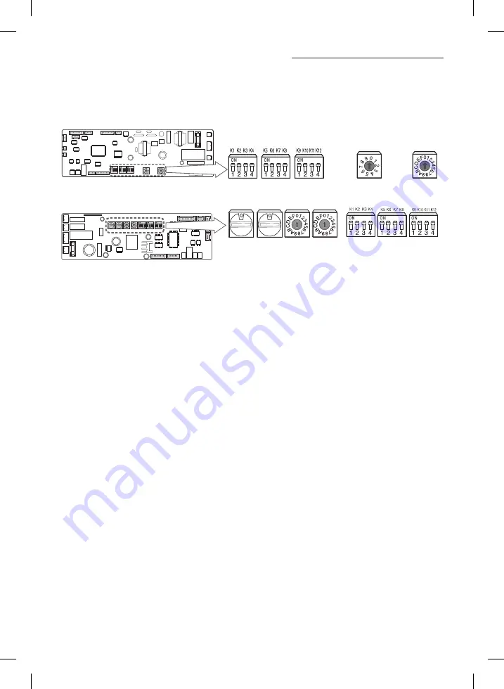
Assigning address to indoor unit

1.  Before installing the indoor unit, assign an address to the indoor unit according to the air conditioning system plan.
2.  The address of the indoor unit is assigned by adjusting MAIN(SW02).

MH

✴✴✴

FSBA

SW05

SW06

SW07

SW02 MAIN

SW04 RMC

MH

✴✴✴

FMBA

SW05

SW06

SW07

SW04 

RMC

SW03 

RMC

SW02 

MAIN

SW01 

MAIN

3.  The MAIN address is for communication between the indoor unit and the outdoor unit. Therefore, you must set it to 

operate the air conditioner properly.

4.  It is required to set the RMC address if you install the wired remote control and/or the centralized control.
5.  If you install optional accessories such as the wired remote control, centralized control, etc. see an appropriate installation 

manual.

6.  If an optional accessory is not installed, you do not have to set the RMC address. However, adjust K1 and K2 switches of 

the SW04(SW05) DIP switch to "ON" position in this case.

FJM IDU-PH_Cassette type_IM_31595A-04_EN.indd   20

2015-11-16   오후 4:52:23

Summary of Contents for MH FSBA Series

Page 1: ...FJM IDU PH_Cassette type_IM_31595A 04_EN indd 26 2015 11 16 4 52 24...

Page 2: ...EN ES PT Cassette Type Series MH FSBA MH FMBA Air Conditioner installation manual imagine the possibilities ThankyouforpurchasingthisSamsungproduct FJM IDU PH_Cassette type_IM_31595A 04_EN indd 27 201...

Page 3: ...9 336 EEC and the Directive on pressurized equipment 97 23 EEC f f The manufacturer shall not be responsible for damage originating from unauthorized changes or the improper connection of electric and...

Page 4: ...uctions on how to operate the air conditioner to the user f f Do not use the air conditioner in environments with hazardous substances or close to equipment that release free flames to avoid the occur...

Page 5: ...e earth wire to the gas pipe water pipe lighting rod or telephone wire If earthing is not complete electric shock or fire may occur Install the circuit breaker If the circuit breaker is not installed...

Page 6: ...imum space around the unit as shown in the drawing f f In scarcely ventilated areas f f On surfaces that are unable to support the weight of the unit without deforming breaking or causing vibrations d...

Page 7: ...295 27 inch to be respected f f Leave enough clearance beneath the indoor unit to enable the filters to be removed without hindrance f f Maintain sufficient clearance around the indoor unit f f Make...

Page 8: ...06 ormore 1500mm 59 06 ormore The units must be installed according to distances declared in order to permit accessibility from each side either to guarantee correct operation of maintenance or repai...

Page 9: ...escription Liquid pipe connection 6 35 1 4 Gas pipe connection 9 52 3 8 Drain pipe connection OD 29 1 14 ID 25 0 98 Power supply connection Air discharge grille Air suction grille Dimension and weight...

Page 10: ...9 Suspension position 321 12 64 288 11 34 Suspension bolt 4 M8 M10 Freshairintakehole Unit mm inch No Name Description 030 035 052 Liquid pipe connection 6 35 1 4 6 35 1 4 Gas pipe connection 9 52 3 8...

Page 11: ...operations on the indoor unit 4 Screw eight nuts to the suspension bolts making space for hanging the indoor unit You must install more than four suspension bolt when installing the indoor unit 5 Che...

Page 12: ...ftover nitrogen could cause internal leakage Unscrew the pinch pipe at the end of each refrigerant pipe RESULT All inert gas escapes from the indoor unit To prevent dirt or foreign objects from gettin...

Page 13: ...ulator which is thick enough to cover the refrigerant pipe to protect the condensate water on the outside of pipe falling onto the floor and the efficiency of the unit will be better 3 Cut off any exc...

Page 14: ...9 7 mm 0 7598 0 7756 5 Check that the flaring is correct referring to the illustrations below for examples of incorrect flaring Flare nut Connectingpipe Indoor outlet pipe Inclined Damaged surface Cra...

Page 15: ...r separately around each refrigerant pipe Always make the seam of pipes face upwards The insulation has to be produced in full compliance of European regulation reg EEC EU 2037 2000 that requires the...

Page 16: ...120 C 248 F 12 70 1 2 19 05 3 4 T13mm 0 51 T13mm 0 51 Gas pipe 6 35 1 4 T13mm 0 51 T19mm 0 75 9 52 3 8 T19mm 0 75 T25mm 0 98 12 70 1 2 15 88 5 8 19 05 3 4 When installing insulation in places and cond...

Page 17: ...supplied Insulation cover drain Insulation drain pipe Insulation cover band Band Adhesives Drainpipe Indoor Unit Check that the indoor unit is level with the ceiling by using the leveler Install air...

Page 18: ...ose Testing the drainage You should test drainage after completing the installation Prepare a little water about 1 0 liter 1 0 quart 1 Open the cover water supply intake 2 Pour water into the water su...

Page 19: ...screw on the electrical component box and remove the cover plate 2 Route the connection cord through the side of the indoor unit and connect the cable to terminals refer to the figure below 3 Route th...

Page 20: ...they are connected to the corresponding F3 and F4 terminal MH FSBA Indoor Unit PCB F1 F2 V1 V2 1 L 2 L F1 F3 F2 F4 V1 V2 Indoor unit rerminal block Accessory in the remote control CN32 CN33 WHT BLU Wi...

Page 21: ...oor unit and the outdoor unit Therefore you must set it to operate the air conditioner properly 4 It is required to set the RMC address if you install the wired remote control and or the centralized c...

Page 22: ...6 K7 K8 SW06 SW06 K5 Indoor temperature compensation for heating mode 2 C 3 6 F 5 C 9 F K6 Filter time 1000 HR 2000 HR K7 K8 MH FMBA No Function ON OFF SW06 K5 Indoor temperature compensation for heat...

Page 23: ...fety net 2 Fix the safety net to the electric component cover box with four screws as indicated The electric component box cover The safety net Air blocking kits 1 When installing the unit depending o...

Page 24: ...mixed operation X X X Error of indoor fan motor Below 450RPM for 15 minutes X X X X Error of outdoor temperature sensor Error of COND sensor Error of DISCHARGE sensor X X X 1 No communication for 2 m...

Page 25: ...E 4 Compressor down due to 6th detection of freezing X X Displayed on appropriate indoor unit which is operating Displayed on outdoor unit Error of float switch X X X Error of setting option switches...

Page 26: ...25 ENGLISH Memo FJM IDU PH_Cassette type_IM_31595A 04_EN indd 25 2015 11 16 4 52 24...

Reviews: