


4-2 Factory Mode Adjustments
4-2-1 Entering Factory Mode
1.
To enter “Service Mode” Press the remote -control keys in this sequence :
- If you do not have Factory remote - control
- If you have Factory remote - control
4-2-2 Factory Mode Tree
4 Alignments and Adjustments
4-2
LW17M24C/LW20M21C
1. Calibration
1. Calibration
VCTi
PC
2. Option
INFO
Menu
3. W/B
4. ADC
5. VCTi 127
6. ACC/ACM
7. Test Pattern
0
8. Bus Stop
off
9. Check Sum
0
10. Reset
T- VNC17(20) - PEU-0003 2004/04/20
( 1) RF, VIDEO, S-VIDEO :
Factory Mode
Calibration
V CTi
Enter
(2) PC : adjust in VGA MODE.
Based on Master device
execute Auto Adjustment in Cross Hatch (also called Combination) (Model : 10, Pattern : 25)
(VI DEO SIGNAL GENERATOR M SPG-925F)
After adjusting 16 Gray Pattern (Model : 10, Pattern : 17)
Factory Mode
Calibr ation
PC
Enter
(3) check 4.ADC of Factory Mode. Adjustment can be done as below.
Value variation can be 10~20.
+_
Summary of Contents for LW17M24C
Page 7: ...Memo 2 Product Specifications 2 4 LW17M24C LW20M21C ...
Page 11: ...Memo 3 Disassembly and Reassembly 3 4 LW17M24C LW20M21C ...
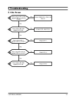
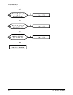
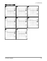
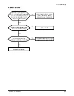
Page 19: ...5 Troubleshooting LW17M24C LW20M21C 5 3 WAVEFORMS 1 2 5 3 6 4 4 7 8 ...
Page 22: ...Memo 5 Troubleshooting 5 6 LW17M24C LW20M21C ...
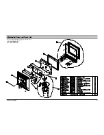
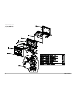
Page 24: ...6 Exploded View Parts List 6 2 LW17M24C LW20M21C 6 2 LW20M21C ...
Page 50: ...9 Schematic Diagrams 9 2 LW17M24C LW20M21C Memo ...
Page 52: ...10 PCB Layout 10 2 LW17M24C LW20M21C Memo ...
Page 54: ...11 Schematic Diagrams 11 2 LW17M24C LW20M21C 1 2 5 3 6 4 7 8 ...
Page 56: ...11 Schematic Diagrams 11 4 LW17M24C LW20M21C 9 ...
Page 62: ...11 Schematic Diagrams 11 10 LW17M24C LW20M21C Memo ...
Page 64: ...www s manuals com ...


