10 Operating Installations and Installation
10-12
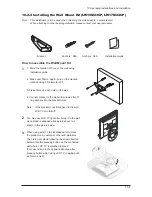
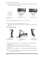
Adjust LCD TV to the hook on the bracket and move in the direction of the arrow(Left) so that LCD
TV can be completely fixed to the bracket.
Remove Installation Guide after completing setup of LCD TV on the wall.
4
5
Push the LCD TV up and shift to the right to detach it from bracket.
When moving or transferring to other areas, reverse No. 4 procedure so as to disconnect LCD TV
with ease.
6
When bracket is assembled
on the wall
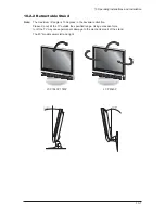
(1) Angle adjustment section
of general stand-besd LCD
TV
(2) Angle abjustment section
while converting the form
(1->3, 3->1)
(3) Angle adjustment section
of wall-mounted LCD TV
How to hang monitor up on a hook
When installation is completed
- How to adjust an angle
1. Picture (1) shows the adjustment angle (0
~ 13
) when you use LCD TV in its general form (stand-
based LCD TV).
2. Excessive tilting can turn LCD TV over which might cause damage to LCD TV.
Picture (2) shows the adjustment angle (13
~ 80
) when you convert stand-based LCD TV into wall-
mounted one.
3. Picture (3) shows the adjustment angle (0
~ 10
) when you use wall-mounted LCD TV after fixing it to
wall.
Note : Picture (2) shows the angle adjustment section while LCD TV is being converted from stand-based
one to wall-mounted one or vice versa.
Summary of Contents for LW15M23CP
Page 6: ...Memo 1 Precautions 1 4 ...
Page 23: ...4 Troubleshooting 4 3 WAVEFORMS 1 2 5 3 6 4 4 7 8 ...
Page 26: ...4 Troubleshooting 4 6 Memo ...
Page 29: ...5 Exploded View Parts List 5 3 5 2 LW17M24CP T0003 M0215 T0447 M0147 M0003 M0014 M0013 ...
Page 31: ...5 Exploded View Parts List 5 5 5 3 LW20M21CP T0003 M0215 M0147 M0014 M0013 M0014 ...
Page 63: ...7 Block Diagrams 7 1 7 Block Diagram ...
Page 64: ...Memo 7 Block Diagrams 7 2 ...
Page 66: ...8 Wiring Diagrams 8 2 Memo ...
Page 68: ...9 Schematic Diagrams 9 2 1 2 5 3 6 4 7 8 ...
Page 70: ...9 Schematic Diagrams 9 4 9 ...
Page 73: ...9 Schematic Diagrams 9 7 ...
Page 74: ...9 Schematic Diagrams 9 8 ...
Page 76: ...9 Schematic Diagrams 9 10 ...
Page 78: ...9 Schematic Diagrams 9 2 1 2 5 3 6 4 7 8 ...
Page 80: ...9 Schematic Diagrams 9 4 9 ...
Page 83: ...9 Schematic Diagrams 9 7 ...
Page 84: ...9 Schematic Diagrams 9 8 ...
Page 86: ...9 Schematic Diagrams 9 10 ...
Page 88: ...9 Schematic Diagrams 9 2 1 2 5 3 6 4 7 8 ...
Page 90: ...9 Schematic Diagrams 9 4 9 ...
Page 93: ...9 Schematic Diagrams 9 7 ...
Page 94: ...9 Schematic Diagrams 9 8 ...
Page 96: ...9 Schematic Diagrams 9 10 ...
Page 126: ...12 PCB Layout 12 2 12 1 2 Power board LW15M23CP ...
Page 127: ...12 PCB Layout 12 3 12 1 2 Power board LW17M24CP LW20M21CP ...
Page 128: ...12 PCB Layout 12 4 Memo ...
Page 129: ...13 Circuit Descriptions 13 1 13 Circuit Descriptions 13 1 Overall Block Structure ...
Page 130: ...13 Circuit Descriptions 13 2 13 2 1 MAIN BOARD POWER TREE 13 2 Partial Block Description ...
Page 132: ...13 Circuit Descriptions 13 4 ...
Page 133: ...13 Circuit Descriptions 13 1 13 Circuit Descriptions 13 1 Overall Block Structure ...
Page 134: ...13 Circuit Descriptions 13 2 13 2 1 MAIN BOARD POWER TREE 13 2 Partial Block Description ...
Page 136: ...13 Circuit Descriptions 13 4 ...

